INSTALLATION SM1500
Page 4 - 3 DELTA ELEKTRONIKA B.V. rev. August 2018
8) Ethernet / IEEE488 / RS232 PRO GRAMMING
• Set DIP switch 1 on SW1 in po si tion OFF for pro gram ming
with the PSC-ETH, the PSC-488 or the PSC-232.
With DIP switch 1 in this po si tion, the sig nals Vprog (pin 11)
and Iprog (pin 3) are dis abled on CON E. All the other sig -
nals can still be used. For Ethernet pro gram ming CON H
must be used, CON F and G can be used for the user in-
and out puts.
For IEEE488 also CON H must be used for pro gram ming.
For RS232 pro gram ming CON F and G must be used.
• Set the unit in RE MOTE CV for volt age pro gram ming
and/or in RE MOTE CC for cur rent pro gram ming us ing the
SCPI com mands (see man ual PSC) or us ing the RE -
MOTE/LO CAL but ton on the unit. Push this but ton sev eral
times un til the right set ting is ac ti vated. Set ting the unit in
RE MOTE or LO CAL will cause the out put to shut down to
avoid ac ci den tal dam age to the load. Turn it on again us ing
the SCPI com mand or with the OUT PUT ON/OFF but ton.
• Set DIP switch 1 on SW1 in po si tion ON to enable CON E
again for an a log pro gram ming.
In this po si tion volt age and cur rent pro gram ming on CON F
and H is dis abled. The other func tions and sig nals can still
be pro grammed and read back.
9) MON I TORING OUT PUTS
• The 5 V level is com pat i ble with most in ter faces.
• The mon i tor ing out puts can drive a me ter di rectly
(see fig. 4 - 4).
10) STATUS OUT PUTS
• The sta tus out puts have a sep a rate Ø con nec tion (pin 8) to
avoid un wanted off sets in the pro gram ming. This pin is pro -
tected with a 650 mA self re set ting fuse (F27_2 on P647).
11) RE MOTE SENSING
• Re move the links on the SENSE BLOCK (on rear panel)
and con nect sense leads (thin shielded mea sur ing wires)
to S+ and S– (see fig 4 - 5 and fig. 4 - 6).
• With re mote sens ing the volt age on the load can be kept
con stant. The volt age drop in the load leads will be com -
pen sated. This fea ture is not rec om mended for nor mal use,
be cause it can eas ily give prob lems.
• Max. 2 V per load lead can be com pen sated. Note that the
volt age drop in the leads de creases the max. out put volt -
age rat ing. In fig. 4 - 7 it can be seen that on a 15 V power
sup ply only 11 V will be avail able on the load when 2x 2 V
com pen sa tion is used.
• In or der to pre vent in ter fer ence, it is ad vis able to twist the
sense leads. To min i mize the in duc tance in the load leads
keep the leads close to each other. The in duc tance of the
loads leads could give a prob lem with pul sat ing loads. In
this case a large elec tro lytic ca pac i tor (Cd) in se ries with a
damp ing re sis tor (Rd) both in par al lel with the load will (see
fig. 4 - 6). Check that the ca pac i tor Cd in com bi na tion with
the load leads and re sis tor Rd forms a well damped cir cuit.
• Since the volt me ter is in ter nally con nected to the sens ing
ter mi nals, it will au to mat i cally in di cate the volt age on the
load. Note that the volt age mea sured on the load will be
lower than on the out put ter mi nals.
• The Over Volt age Limit mea sures the volt age on the out put
ter mi nals, so the OVL set ting should be in creased by the
to tal volt age drop in the load leads.
12) BAT TERY CHARGER
• The CV / CC reg u lated power sup plies are ideal bat tery
charg ers. Once the out put is set at the cor rect volt age the
bat tery will charge con stantly with out over charg ing.
This can be use ful for emer gency power sys tems.
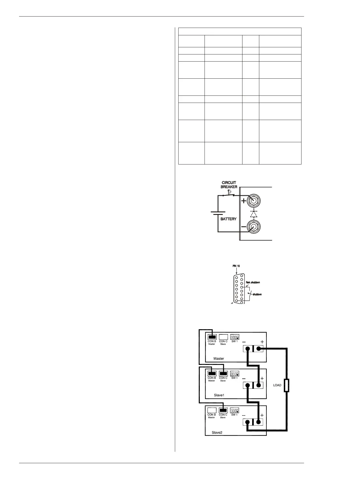
• Pro tec tive mea sures
Use a CIR CUIT BREAKER in se ries in or der to pro tect the
power sup ply from ac ci den tal re verse con nec tion (see
fig. 4 - 8). The cir cuit breaker should have a DC volt age rat -
ing twice the bat tery volt age. Use the very fast type (Z), a
Sug gested circuit breakers for pro tec tion power sup ply
Model Type num ber
circuit breaker
Brand Re marks
SM15-100 HTI101 B 100 GE -
SM35-45 S281 UC-Z 50 ABB -
SM52-30 S281 UC-Z 32 ABB ex tra par al lel di ode
on out put needed
BYV255V-200
SM52AR60 S281 UC-Z 63 ABB ex tra par al lel di ode
on out put needed
BYV255V-200
SM70-22 S281 UC-Z 25 ABB -
SM120-13 S281 UC-Z 16 ABB ex tra par al lel di ode
on out put needed
BYV255V-200
SM300-5 S282 UC-Z 6
use with 2 poles
in se ries
ABB ex tra par al lel di ode
on out put needed
2xBYT261PIV400
SM400AR8 S282 UC-Z 10
use with 2 poles
in se ries
ABB ex tra par al lel di ode
on out put needed
2xBYT261PIV1000
ta ble 4 - 2
fig. 4 - 8
Charg ing bat tery with a cir cuit breaker in se ries
fig. 4 - 9
Re mote ShutDown with switch
fig. 4 - 10
Mas ter / Slave se ries con nec tion
 Loading...