GENERAL SM1500
12 / 22 DELTA ELEKTRONIKA B.V. rev. Jan. 2021
DC VOLTAGE AND CURRENT LIMIT
The Voltage Limit will protect your circuit from unwanted high
voltages. A high DC output voltage could be caused by
accidental interruption of leads, accidentally turning up the
voltage potmeter, a programming error or a defect in the
power supply. The Voltage Limit circuit uses a separate
voltage divider connected directly to the output terminals.
The Current Limit protects your circuit from unwanted high
currents.
The Voltage and Current Limits maintain the output to a safe
preset value.
They do not trip, so no resetting is needed after a fault. It can
be very handy to have hardware limits when the power supply
is programmed.
The limits can easily be set by pressing the DISPLAY LIMITS
button and adjusting the potentiometers with a screwdriver.
The LED’s next to the potmeters indicate the activity of each
limit, also the LIM-status output will be "1".
3.33
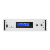
POTENTIOMETERS AND ENCODERS
At the front panel, standard every unit is equipped with knobs
for the CV and CC controls and with screwdriver adjustment
for the Voltage and Current Limit.
Optional there is the possibility for digital encoders for the
CV/CC-controls, with a very long life time and intelligent
functions such as variable coarse/fine pitch adjustment,
locking of CV/CC-settings and a selectable start-up voltage
(start at 0V/0A or at last settings).
The standard units have analog potentiometers for the
CV/CC-controls . Optional they can be equipped with
screwdriver adjustment for CV/CC-settings at the front panel
or also with digital encoders (option P220). See fig. 3 - 23 for
option P001.
3.34
A low noise blower cools the unit. The speed of the fan
depends on the temperature of the internal heatsink. Normally
at 50 °C ambient and full load the fan will not work at full
speed.
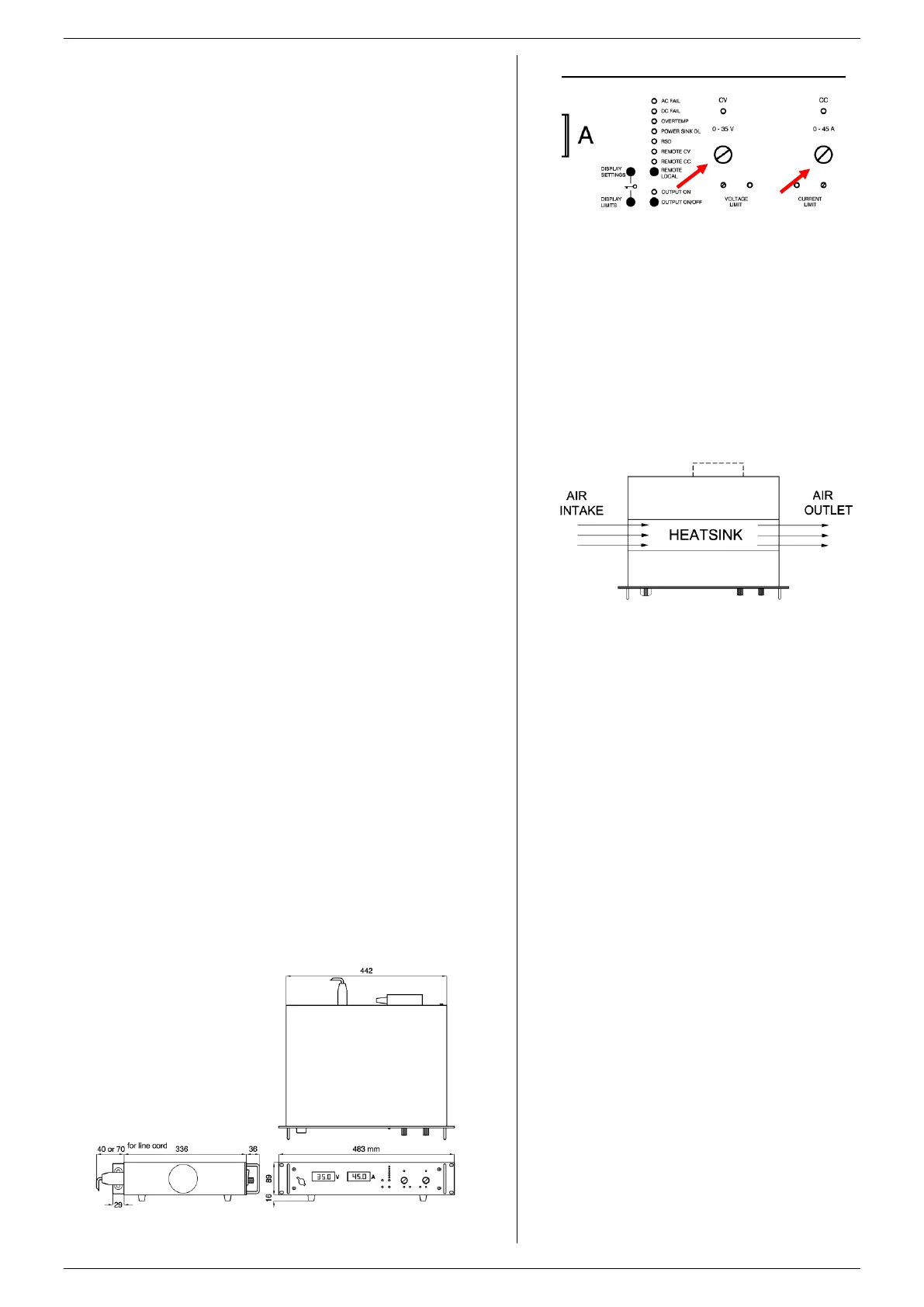
A special feature is that the fan blows through a tunnel where
the heatsinks are situated, the delicate control circuitry is
separated and will not be in the airflow path (see fig. 3 - 24).
Because the air enters at the left and exits at the right side, it
is possible to stack the power supplies, no distance between
the units is required. Only the ventilation openings at the left
and right side should be free.
For long life the temperature of the air entering on the left
side, should be below 35 °C under normal conditions. Under
extreme conditions it should be below 50 °C.
3.35
fig 3 - 23
Screwdriver adjustment at front panel.
fig 3 - 24
The fan blows through the tunnel, where the
heatsinks are situated. Take care to leave the air
outlet unobstructed.
fig 3 – 25 Unit dimensions.
 Loading...