INSTALLATION SM1500
15 / 22 DELTA ELEKTRONIKA B.V. rev. Jan. 2021
ISOLATED ANALOG PROGRAMMING
For programming via the ISO AMP CARD, set DIP switch 1
on SW1 in the position Right.
When the ISO AMP CARD is built inside the unit, CON E has
been covered or removed. Use CON H instead. The pinning
of CON H is equal to the pinning of CON E.
For further operating instructions, see previous paragraph.
4.9
IEEE488 / RS232 PROGRAMMING
Set DIP switch 1 on SW1 in position Right for programming
with the PSC-488 using CON H or programming with the
PSC-232 using CON F and G. With DIP switch 1 in this
position, the signals V
prog
(pin 11) and I
prog
(pin 3) are disabled
on CON E. All the other signals can still be used.
Set the unit in REMOTE CV for voltage programming and/or
in REMOTE CC for current programming using the SCPI
commands (see manual PSC) or using the REMOTE/LOCAL
button on the unit. Push this button several times until the
right setting is activated. Setting the unit in REMOTE or
LOCAL will cause the output to shutdown to avoid accidental
damage to the load. Turn it on again using the SCPI
command or with the OUTPUT ON/OFF button.
Set DIP switch 1 on SW1 in position Left to enable CON E
again for analog programming. In this position voltage and
current programming on CON F and H is disabled. The other
functions and signals can still be programmed and read back.
4.10
The 5 V level is compatible with most interfaces.
The monitoring outputs can drive a meter directly (fig. 4 - 4).
4.11
The status outputs have a separate Ø connection (pin 8) to
avoid unwanted offsets in the programming. This pin is
protected with a 650 mA self resetting fuse (F27_2 on P650).
4.12
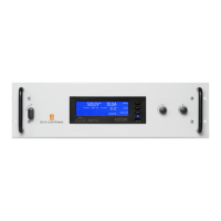
DC LOAD SENSING (REMOTE SENSING)
Remove the links on the SENSE BLOCK (on rear panel) and
connect sense leads (thin shielded measuring wires) to S+
and S–. See fig. 4 - 5 and fig. 4 - 6.
With remote sensing the voltage on the load can be kept
constant. The voltage drop in the load leads will be
compensated. This feature is not recommended for normal
use, because it can easily give problems.
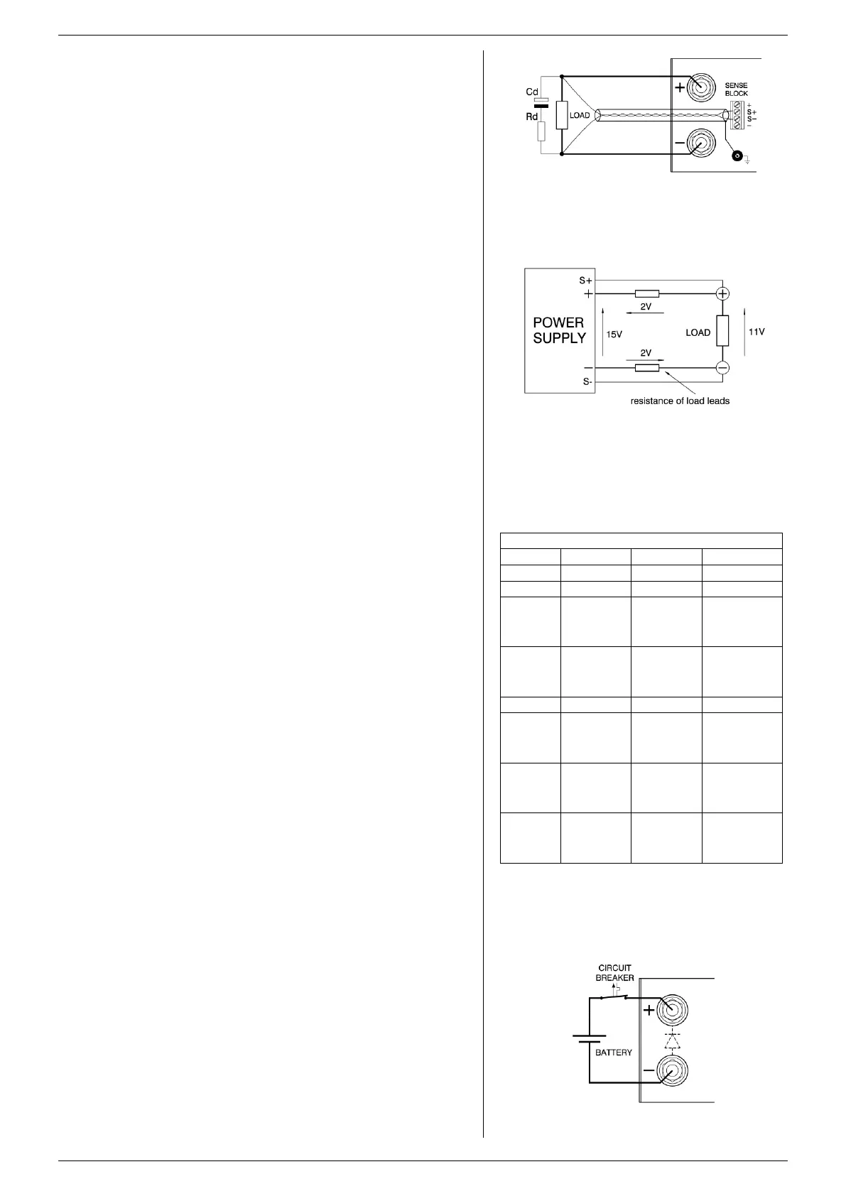
Max. 2 V per load lead can be compensated. Note that the
voltage drop in the leads decreases the max. output voltage
rating. In fig. 4 - 7 it can be seen that on a 15 V power supply
only 11 V will be available on the load when 2x 2 V
compensation is used.
In order to prevent interference it is advisable to twist the
sense leads. To minimize the inductance in the load leads
keep the leads close to each other. The inductance of the
loads leads could give a problem with pulsating loads. In this
case a large electrolytic capacitor (C
d
) in series with a
damping resistor (R
d
) both in parallel with the load will help
(see fig. 4 - 6). Check that the capacitor C
d
in combination
with the load leads and resistor R
d
forms a well damped
circuit.
Since the voltmeter is internally connected to the sensing
terminals, it will automatically indicate the voltage on the
load. Note that the voltage measured on the load will be
lower than on the output terminals.
The Over Voltage Limit measures the voltage on the output
terminals, so the OVL setting should be increased by the total
voltage drop in the load leads.
4.13
The CV / CC regulated power supplies are ideal battery
chargers. Once the output is set at the correct voltage the
battery will charge constantly without overcharging. This can
be useful for emergency power systems.
fig 4 - 6
Remote sensing with shielded wires.
fig 4 - 7
remote sensing, voltage drop on load leads subtracts
from the maximum output.
fig 4 - 8
Charging a battery with a circuit breaker in series.
Suggested circuit breakers for protection power supply
extra parallel
diode on output
needed
BYV255V-200
extra parallel
diode on output
needed
BYV255V-200
extra parallel
diode on output
needed
BYV255V-200
S282 UC-Z 6
use with 2
poles in series
extra parallel
diode on output
needed 2x
BYT261PIV400
S282 UC-Z 10
use with 2
poles in series
extra parallel
diode on output
needed 2x
BYT261PIV1000
table 4 -2
Circuit breakers for protection.
 Loading...