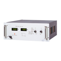
GENERAL SM1500
6 / 22 DELTA ELEKTRONIKA B.V. rev. Jan. 2021
The SM15-100, SM35-45, SM52-30, SM52-AR-60, SM70-22,
SM120-13, SM300-5 and the SM400-AR-8 can either be
used as a constant voltage source with current limiting or as
a constant current source with voltage limiting. The change of
mode occurs sharply at the crossing of the voltage and
current settings. Fig. 3 - 1 shows the output ranges.
The SM52-AR-60 and the SM400-AR-8 feature an
AUTORANGING facility where the power supply
automatically switches over between two current ranges. This
switching, which is unnoticeable for the user, results in a
versatile power supply with twice the output voltage range.
This means that for the SM52-AR-60 the maximum output
power of 1560 W is available at both 26 V and 52 V. For the
SM400-AR-8 this is 1600 W at both 200 V and 400 V.
DISPLAY CV/CC SETTINGS FUNCTION
The settings of the voltage and current control (also when
programmed) can be observed on the front panel meters by
pressing the Display CV/CC Set- tings button. This allows the
current limit to be set when operating in the CV the voltage
limit to be set C mode without opening the load leads.
OVERLOAD PROTECTION
The power supply is fully protected against all overload
conditions, including short circuit.
3.2
The power supplies have a wide AC input voltage range.
The unit needs a single phase input voltage. At voltages
below about 120 VAC the output power has to be derated,
see specifications in the datasheet.
3.3
The unit has active power factor correction (PFC). The input
current will therefore almost be a sine wave. This means that
the RMS-value and the harmonic distortion of the AC input
current will be relatively low.
The peak inrush current is electronically limited. Switching on
and off repeatedly will not result in excessive currents like
with NTC circuits.
3.4
The unit consumes very little power when in standby. This
makes it possible to leave the AC input power on when the
output is disabled using the Output On/Off push button on
front panel or the Remote ShutDown input (pin 5 on
connector CON E on the rear panel).
3.5
The efficiency is very high and constant over a wide DC
output current range.
High efficiency means low power loss and low heat
generation.
3.6
The specified CV-load regulation value is measured directly
on the DC power terminals. This is because at high current, a
few cm of cable can have a voltage drop of several mV.
3.7
For accurate CC-load regulation, do not use external voltage
sensing.
A voltage between S- and minus output will create an error of
about 0.04 % per volt.
A voltage between S+ and + is not critical. The CC-stability is
also affected by external voltage sensing.
Note: when the unit operates in CC-mode, the DCF-LED will
be on. When the unit is in CC-mode most of the time, it is
possible to disable the LED with DIP switch 3 on SW1 (rear
panel).
fig 3 - 1
DC Output voltages and currents.
Every point in hatched area can be used
fig 3 - 3
Measuring ripple voltage
RIGHT!
fig 3 - 2
Measuring ripple voltage
WRONG!

 Loading...


