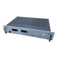
Do you have a question about the Delta Elektronika SM 70-AR-24 and is the answer not in the manual?
| Output Voltage | 24 V |
|---|---|
| Power Rating | 1680 W |
| Efficiency | 90% |
| Protections | Overvoltage, overcurrent, short circuit |
| Operating Temperature | 0-50 °C |
Safety precautions for operation, service, and repair. Avoid hazards like live circuits and improper parts.
Connect chassis to AC Power Supply mains for shock hazard minimization and follow installation category II guidelines.
Fuses must be changed by authorized personnel. Do not exceed input voltage and frequency ratings.
Allowed only by authorized personnel; unit return for repairs is required for modifications.
Specifies operating conditions: indoor use, temperature, humidity, altitude, pollution degree, and safety symbols.
Correct disposal of the product in the European Union for responsible recycling.
Describes output modes, autoranging, display settings, and overload protection.
Covers input voltage range, active PFC input current, and low standby power consumption.
Details CV/CC regulation, efficiency, and output ripple/noise characteristics.
Programming output via external analog voltage and preventing earth loops.
Using Ethernet, IEEE 488, RS232 controllers for programming and status monitoring.
Describes monitor outputs for current/voltage and various status output signals.
Details the two status relay outputs with change-over contacts for DCF and ACF signals.
Defines the meaning of status signals like OT, CC, PSOL, ACF, and DCF.
Explains the functions of the dipswitches 1-4 on the rear panel switch SW1.
Describes how to use Remote Shutdown input and the Interlock connector for safety.
Covers programming speed, handling pulsating loads, and insulation testing.
Details RFI filters, operating temperature range, and derating requirements.
Explains thermal protection, hold-up time, turn-on delay, and inrush current.
Describes how to keep load voltage constant by compensating for lead voltage drop.
Guidelines for connecting units in series or parallel for increased voltage or current.
Explains how to use units as building blocks to form larger systems.
How to set and use voltage and current limits for safe operation.
Describes potentiometer types and the unit's internal cooling fan system.
Provides the physical dimensions of the power supply unit.
Step-by-step guide for initial unit setup, including checks and connections.
How to activate and deactivate the Keylock function to protect output control.
Configuring analog programming via connector CON E by setting dipswitch 1.
Programming via ISO AMP Card (CON H) and digital interfaces like Ethernet, IEEE 488, RS232.
Using monitoring outputs to drive meters and understanding status output signals.
Implementing remote sensing to maintain constant load voltage by compensating lead drops.
Using the unit as a battery charger and operating remote shutdown.
Connecting units in series for higher voltage with Master/Slave control.
Considerations for parallel operation of fast programming versions, testing with load.
Connecting units in mixed series/parallel configurations using adapters.
Specifies acceptable temperature and humidity ranges for operation and storage.
Recommendations for using power supplies in aggressive environments like galvanic industry.
No routine maintenance needed; ensure cooling is unobstructed and inspect fan regularly.
Contacting support for repairs and troubleshooting steps for 'No Output' condition.
Steps to resolve programming errors, large output errors, and programming offsets.
Checking fuses for status output failures and identifying causes.
Troubleshooting master/slave parallel problems and high output voltage.
Interpreting various LED indicators (OT, ACF, DCF, PSOL, etc.) for fault diagnosis.
Handling persistent problems and general troubleshooting advice.
General calibration notes and how to calibrate digital meters.
Detailed procedures for calibrating current monitor offset and maximum current range.


 Loading...