INSTALLATION SM15K
16 / 32 DELTA ELEKTRONIKA B.V. rev. January 2021
OPTIONAL MASTER / SLAVE CONTROL
For easy series or parallel operation the Master / Slave
interface is advised.
See chapter 7 for more information about the M/S interface.
5.12
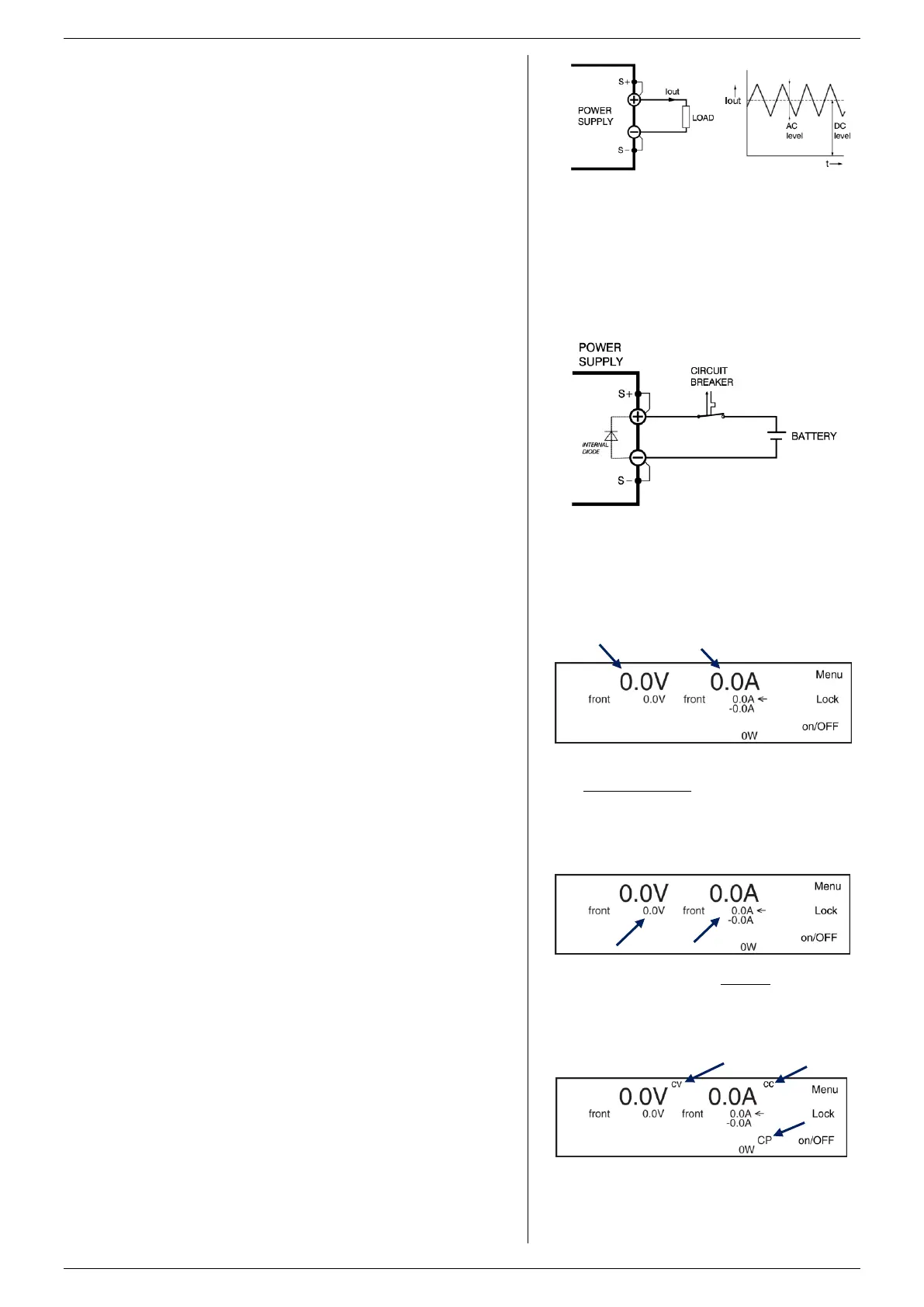
To avoid overheating the output capacitors, the AC
component of the DC load current should be limited (see
fig. 5 - 13).
One method of reducing the AC current through the output
capacitor is by using a large external electrolytic capacitor in
parallel with the load. Care must be taken so that the
capacitor in combination with the lead inductance will not form
a series resonant circuit!
When using remote sensing on a pulsating load (for instance
a DC-motor), use a capacitor in series with a resistor over the
load (see fig. 5 - 10). With this the AC-component caused by
the pulsing of the load is filtered.
The CV / CC regulated power supplies are ideal battery
chargers. Once the output is set at the correct voltage the
battery will charge constantly without overcharging. This can
be useful for emergency power systems.
Use a Circuit Breaker in series in order to protect the power
supply from accidental reverse connection (see fig. 5 - 14).
The unit has a reverse diode in parallel with the output, this
diode and the wiring cannot withstand the thousands of
amperes supplied by a wrongly connected battery.
Contact our support for information on which type of circuit
breaker to use.
5.13
Switch the unit ON by rotating the mains switch on the front
panel clockwise.
The first line in the front display indicates the actual values for
the DC output voltage and current. See fig. 5 - 15.
The second line shows the settings of the controls for the
voltage and current. If the unit is in local operation, the text
'front' is indicated before the settings values. If the unit is set
to remote programming, for example Ethernet programming,
the text 'eth' is indicated. See fig. 5 - 15...19.
The right side of the display shows the texts 'Menu', 'Lock'
and 'on/OFF'. Press the push buttons right from these texts to
operate the following item:
* Menu: This button will enter the main menu of the unit.
See the next chapter for the different choices and settings.
* Lock: Pressing this button for about 5 seconds will lock the
rotary encoders and/or the display menu. Pressing it again
for about 5 seconds, will unlock the encoders and/or the
display menu. This function can be useful to protect the
output from accidental shutdown. See next chapter for exact
possibilities of the 'Lock' function.
* On/Off: This button will switch the power output on or off.
Check if the unit is in local operation: the text before the set
values on the 2nd line must be 'front'. See fig. 5 - 16.
Switch on the output by pressing the on/OFF button - it should
now change to ON/off.
5.13.2 CV, CC & CP CONTROL
Turn both the V- and A-knob a few turns clockwise.
A voltage should now be present on the output.
Under the values for the actual output voltage and current, the
display always shows the settings for the CV-control and for
the CC-control. See fig. 5 - 16.
Depending on the load and the settings, the unit will be either
in CV, CC or in CP mode. See fig. 5 - 17.
Respectively the indication 'CV' will appear on the first line,
next to the actual voltage value. The indication 'CC' will
fig 5 - 13
Pulsating load current.
fig 5 - 14
Charging battery with a circuit breaker in series to
protect the internal diode.
fig 5 - 15
The first line in the display shows the
actual output value for voltage and current.
fig 5 - 16
The second line shows the set value for voltage
and for source current and sink current (with a
minus sign).
fig 5 - 17
A unit is either in CV, CC or CP mode, indicated
next to the actual values of respectively the output
voltage, output current or the output power.
 Loading...

