DELTA ELEKTRONIKA BV SM1540-D SM7020-D SM3004-D
Page 3 - 2 DESCRIPTIONS 1989 rev. May 2008
3) IN PUT CUR RENT
The in put cir cuit has a large se ries choke to im prove the waveform. The re -
sult is: a lower rms in put cur rent, less mains dis tortion and no large peak cur -
rents. The units also have an in rush current limiter and a soft start circuit, for
smooth switch on.
• FUSES- At 220 V: 8 A Slow blow, at 110 V: 16 A Slow blow.
4)
STANDBY IN PUT POWER
The unit consumes very lit tle power when in standby. This makes it possible
to leave the in put power on and use the Re mote Shut Down in put (pin 5 on
prog. connector rear panel) to dis able the out put.
5)
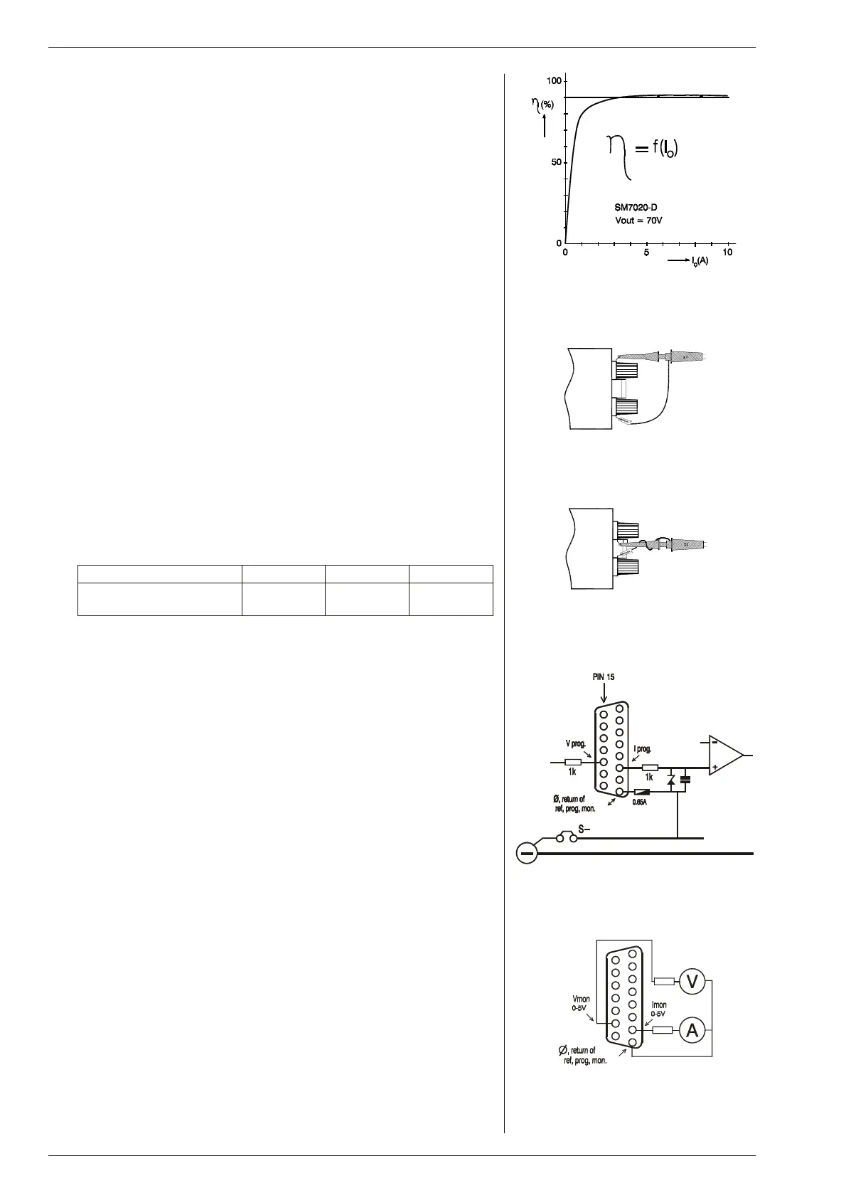
EFFICIENCY
The ef ficiency is very high and constant over a wide output cur rent range,
see fig. 3 - 5. High ef ficiency also means low power loss and low heat gen er-
a tion.
6)
REG U LA TION
The load reg ulation should be measured di rectly on the out put terminals.
A few cm of ca ble can have a voltage drop of several mV (at high cur rent!).
7)
RIPPLE & NOISE
The out put rip ple is very low with al most no spikes.
The rip ple volt age has to be mea sured di rectly on the out put terminals us ing
a probe with very short con nections (to avoid pick up of mag netic fields). See
fig. 3 - 6 and fig. 3 - 7.
• LOW TEM PER A TURE
At –20 °C the CV rip ple in creases to the fol lowing val ues:
8)
PRO GRAMMING IN PUTS
The out put voltage and cur rent can be programmed by an ex ternal an alog
voltage. This pro gramming is very ac curate and lin ear, (non-lin ear ity <
0.15%). The lev els are all standardized on 5 V. Always use a shielded ca ble
for pro gram ming.
The in puts have a protection circuit formed by a series re sistor and a par allel
zener, see fig. 3 - 8. The capacitor limits the speed to a safe value. Note that
the an alog in puts (and outputs) are not floating, but the common is con-
nected to the negative output terminal. Wrong con nec tion of Ø can cause
earth loops which can trip the fuse. After re moving the fault, the fuse will re -
set (PTC-fuse). To pre vent earth loops, use isolated pro gramming with the
ISO AMP MOD ULE
(δ-prod uct).
The pro gramming mode (program and man ual) can be se lected by means of
the prog. switches which are sit uated be low the pro gramming con nector,
see fig. 3 - 10.
9)
IEEE488 / RS232 PRO GRAMMING
The prog. con nector on the power sup ply is both pin and level com patible
with the interfaces PSC-488 mod ule and PSC-232 mod ule (both
δ-prod-
ucts)
.
Voltage and cur rent can easily be pro grammed and read back, also the CC
and OVP sta tus can be read by the computer. Al ways use a shielded ca ble
for pro gram ming.
10)
MON I TORING OUT PUTS
The mon itor outputs give a voltage 0 - 5 V pro portional to the out put cur rent
or volt age. The output cur rent can easily be mea sured without an ex ternal
shunt us ing the I monitor, see fig. 3 - 9. The monitor outputs are buffered by
op-amp’s and protected by se ries re sistors and parallel zeners see fig. 3 -
11. The table in fig. 3 - 12 shows the impedance lev els of the mon itoring out -
puts.
Note: in case of a pul sat ing load, the I mon itor voltage will not ex actly
fig. 3 - 5
Ef fi ciency vc out put current, SM7020-D
DC input, V
out = 70 V
SM1540-D SM7020-D SM3004-D
CV rip ple (rms/pp)
@ −20 °C
6 / 20 mV 10 / 35 mV no change
fig. 3 - 6
Mea sur ing rip ple volt age
WRONG !
fig. 3 - 7
Mea sur ing rip ple volt age
RIGHT !
fig. 3 - 8
Pro gram ming in puts
(in ter nal cir cuit)
fig. 3 - 9
Ex ter nal me ters
us ing mon i tor out puts

 Loading...
