DELTA ELEKTRONIKA BV SM1540-D SM7020-D SM3004-D
Page 3 - 4 DESCRIPTIONS 1989 rev. May 2008
on lighter loads. This is caused by the out put ca pacitors, which
can only be dis charged by the load be cause the power sup ply
cannot sink current.
14)
PRO GRAMMING BAND WIDTH
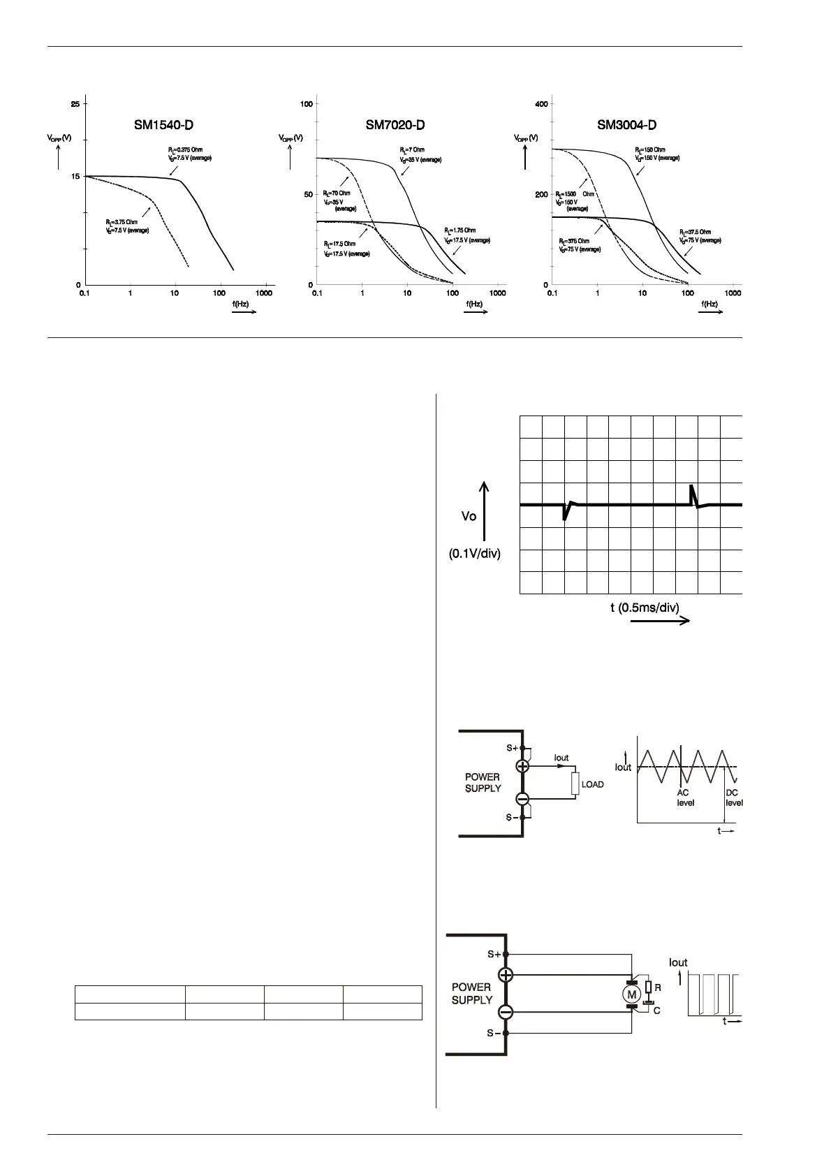
For small sig nals the band width is 50 Hz, but for large sig nals
there is a limitation in the maximum am plitude of the out put wave -
form. The out put ca pacitors limit the max. slew rate. Fig. 3 - 15
shows the maximum peak to peak out put voltage swing as a
function of frequency, with the load as a pa rameter. The higher
the load re sistance the lower the max. am plitude. The mea sure-
ments were car ried out us ing a sine wave. The DC level of the
output is 50 % of the max. out put voltage. On the SM7020-D and
SM3004-D mea surements were also car ried out at 25 % of the
max. output voltage.
15)
RE COVERY TIME
Fig. 3 - 16 shows the recovery time for the SM7020-D at 25 °C, a
50 – 100 % load step and at max imum out put voltage. At –20 °C
the re covery time in creases by 100 μs.
16)
NOISE SUP PRESSION (in put / out put)
The in put / output noise sup pression is mea sured with a pulse
generator (a) in se ries with the line in put or (b) be tween in put and
case (earth). The gen erator should produce a high en ergy pulse
of about 300 V. If there is an electrical con nection be tween the
output and the in put through the os cilloscope, you will get a false
reading. The suppression for the SM3004-D is lower, but the rel-
ative disturbance on the output is comparable to the SM1540-D.
17)
PUL SATING LOAD
To avoid overheating the out put ca pacitors, the AC component
of the load current should be limited. See fig. 3 - 17.
One method of de creasing the AC current through the output ca -
pac i tor is by us ing a large ex ter nal elec tro lytic ca pac i tor in par al -
lel with the load. Care must be taken so that the ca pacitor in
combination with the lead in ductance will not form a series reso-
nant cir cuit!
When us ing re mote sens ing on a pul sating load (for in stance a
DC-motor), use a ca pacitor be tween S+ and + and be tween S-
and - and a se ries re sistor in the sense leads. See fig. 3 - 18. Like
this the AC-component caused by the voltage drop across the
load leads, is fil tered.
fig. 3 - 15
Max. peak to peak out put voltage swing vs frequency
fig. 3 - 16
Re cov ery time SM7020-D
50 - 100 % load step, Vo = 70 V
fig. 3 - 17
Pulsating load current
fig. 3 - 18
Remote sensing on a pulsating load
SM1540-D SM7020-D SM3004-D
AC-level max.
10 Arms 5 Arms 1 Arms

 Loading...
