- -
15
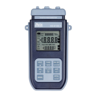
5. open the two module shells: the printed circuit to which the probe must be connected is housed
inside. On the left there are the 1…4 points on which the sensor wires must be welded. The
JP1…JP4 jumpers are in the center of the board. These must be closed with a tin bead for some
type of sensors:
1
2
3
4
Pt100 3 wires
Pt1000
Ni1000
Not Used
Caution! Before welding, pass the probe cable through the fairlead and gasket.
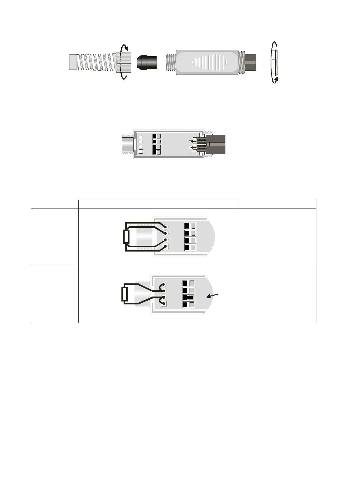
6. Weld the wires as shown in the table:
Sensor TP47 Board connection Jumper to close
Pt100 4 wires
4
JP4
3
JP3
1
JP1
2JP2
Pt100
4 wires
None
Pt1000 2 wires
JP4
4
JP3
3
JP1
1
JP22
Pt1000
2 wires
JP2
Ensure the welds are clean and perfect.
7. Once the welding operation is complete, close the two shells;
8. Insert the gasket in the module;
9. Screw the fairlead and the ring.
10. At the other end of the module, enter the ring with the O-Ring.
11. Make sure the cable is not twisted while you are screwing the fairlead. Now the probe is ready.

 Loading...