4
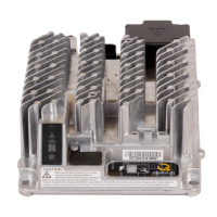
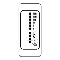
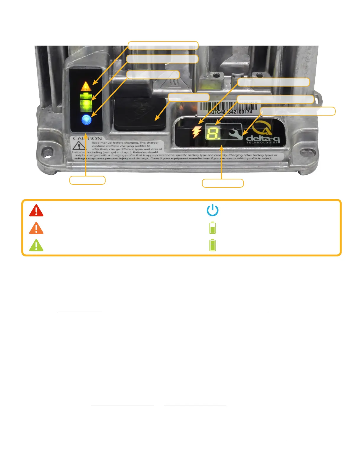
1.0 Charger Interface
Solid red = Charger fault
See display panel for details
Flashing amber = External error condition - caution
See display panel for details
Flashing green = USB port active
Solid green = Safe to remove USB flash drive
Flashing green = Low state of charge
Solid green = High state of charge
Flashing green = High state of charge
Solid green = Charge completed
Solid blue = AC power available
1. The Charging Output Indicator is solid yellow when the charger output is active. Take appropriate
actions while handling the charger, as there is a risk of electric shock.
2. The USB Host Port provides read and write USB functionality. Using a standard USB flash drive, a
user can download charge tracking data, and update the charger’s software and charging profiles.
See the USB Host Port, IC650 Configuration, and Charge Cycle Tracking Data sections for more
information.
3. The Charge Profile / Error Display shows one of four possible codes to indicate different conditions:
‘F’ codes mean that an internal fault condition has caused charging to stop.
‘E’ codes mean that an external error condition has caused charging to stop.
‘P’ codes mean that the charger programming mode is active.
‘USB’ code meaning that the USB interface is active, and the USB flash drive should not be
removed.
The ‘E,’ ‘F’ and ‘P’ codes are followed by three numbers and a period to indicate different conditions
(e.g. E-0-0-4.). See the Charger Fault Codes or Charger Error Codes sections for details on these
conditions and their solutions. ‘P’ codes indicate the charging profile number.
4. The Select Charge Profile Button is used to select a charge profile from those stored on the
charger. Up to 25 charge profiles can be stored. See the Selecting A Charge Profile section for
instructions.
Fault / Error / USB Indicator
Battery Charging Indicator
AC Power Indicator
USB Host Port
Charging Output Indicator
1
Charge Prole / Error Display
2
Select Charge Prole Button
3
Status Bar
Display Panel
 Loading...