EasyManua.ls Logo

Delta-q IC650 - Troubleshoot Manual

Delta-q IC650
58 pages
Print Icon
To Next Page IconTo Next Page
Loading...
IC SERIES
INSTALLATION &
TROUBLESHOOTING GUIDE

Other manuals for Delta-q IC650

Questions and Answers

  • M
    medwardsJul 27, 2025
    What to do if the Delta-q Battery Charger shows a solid red Fault/Error/USB Indicator?
    • P
      Patrick HahnJul 27, 2025
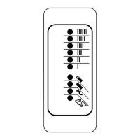
      If your Delta-q Battery Charger displays a solid red Fault/Error/USB indicator, you should read the fault code (e.g., F-0-0-1) number on the Charge Algorithm/Error Display and then refer to the fault code table for guidance.
  • V
    Vanessa GomezAug 2, 2025
    What to do if the Delta-q Battery Charger has a flashing amber Fault/Error/USB Indicator?
    • J
      John CooperAug 2, 2025
      If the Fault/Error/USB Indicator on your Delta-q Battery Charger is flashing amber, read the error code (e.g., E-0-0-1) number shown on the Charge Algorithm/Error Display and consult the error code table.
  • M
    Melanie AguirreAug 9, 2025
    How to fix a Delta-q Battery Charger with no indicator lights?
    • H
      hporterAug 9, 2025
      If your Delta-q Battery Charger has no indicator lights, check the AC voltage and the connection to the wall power outlet.
  • A
    Adriana GonzalezAug 15, 2025
    Why is only the blue AC light on on my Delta-q Battery Charger?
    • W
      William SimmonsAug 15, 2025
      The blue AC light on your Delta-q Battery Charger indicates that the charger is connected to AC power and is waiting for a battery to be connected, or for CAN remote control commands. Charging will begin once the battery voltage rises above 0.1V/cell. Some charging algorithms need a higher battery voltage to start.
  • G
    George CooperAug 20, 2025
    What to do if Delta-q Battery Charger is not working but no error is indicated?
    • P
      phillipsjudyAug 20, 2025
      Remove AC and battery for at least 30 seconds, then retry the charger. If the problem continues, it should be sent back to manufacturer of your vehicle/ machine or the distributor of the charger for servicing.

Summary

Getting Started

High Voltage Safety

Guidelines for safely working with high voltage components in the charger.

Electrical Safety Information

Crucial safety information regarding electrical connections and operation.

Battery Safety Information

Essential safety precautions for handling and charging batteries.

Precautions

Important warnings and advice regarding charger usage and environment.

IC Series Charger Interface

Charger Interface Components Overview

Labels and identifies key components like indicators, ports, and displays.

Indicator Legend

Explains the meaning of various indicator light states and symbols on the charger.

Charger Operation Notes

Provides additional details and clarifications on charger functions and indicators.

Charger Status and Error Codes

Defines different types of status and error codes displayed by the charger.

Charger Operation Modes

Details normal, bulk, absorption, and complete charging states with indicators.

USB Configuration Guide

Step-by-step guide for using a USB flash drive to configure the charger.

Electrical Installation

Rear Panel Connector Identification

Identifies and illustrates the various connectors on the charger's rear panel.

Machine Wiring Best Practices

Discusses wiring considerations for minimizing EMI and ensuring optimal performance.

Cable Management and Routing

Provides recommendations for securing and routing cables for robustness and longevity.

IC650 DC Output

IC650 DC Output Connections & Specs

Details the DC output terminals and recommended wire sizes for IC650.

IC900;1200 DC Output

IC900;1200 DC Output Connections & Specs

Details the DC output terminals and recommended wire sizes for IC900/1200.

IC650 DC Wiring Instructions

IC650 DC Wiring Procedure

Step-by-step guide for connecting DC cabling to the IC650 charger.

IC900 & IC1200 DC Wiring Instructions

IC900 & IC1200 DC Wiring Procedure

Step-by-step guide for connecting DC cabling to IC900/1200 chargers.

Signals & Control Connector

Signals and Control Connector Pinout & Details

Details connector pin assignments, wire colors, and descriptions for signals.

Troubleshooting

Common Symptoms and Actions

Lists common issues and recommended actions for their resolution.

Internal Fault Code Resolution

Explains internal fault codes and customer troubleshooting actions.

External Error Code Resolution

Explains error codes related to external conditions and customer actions.

Software;Algorithm Error Handling

Lists software and algorithm errors and troubleshooting steps.

Configuration Error Handling

Lists configuration errors and troubleshooting steps.

Delta-q IC650 Specifications

General IconGeneral
Input Voltage85-265 VAC
Input Frequency45-65 Hz
Output Power650 W
Efficiency93%
Storage Temperature-40°C to +85°C
ProtectionOver-voltage, Over-temperature, Short-circuit
CommunicationCAN bus
Cooling MethodConvection
Output Voltage12-48 VDC

Related product manuals