11
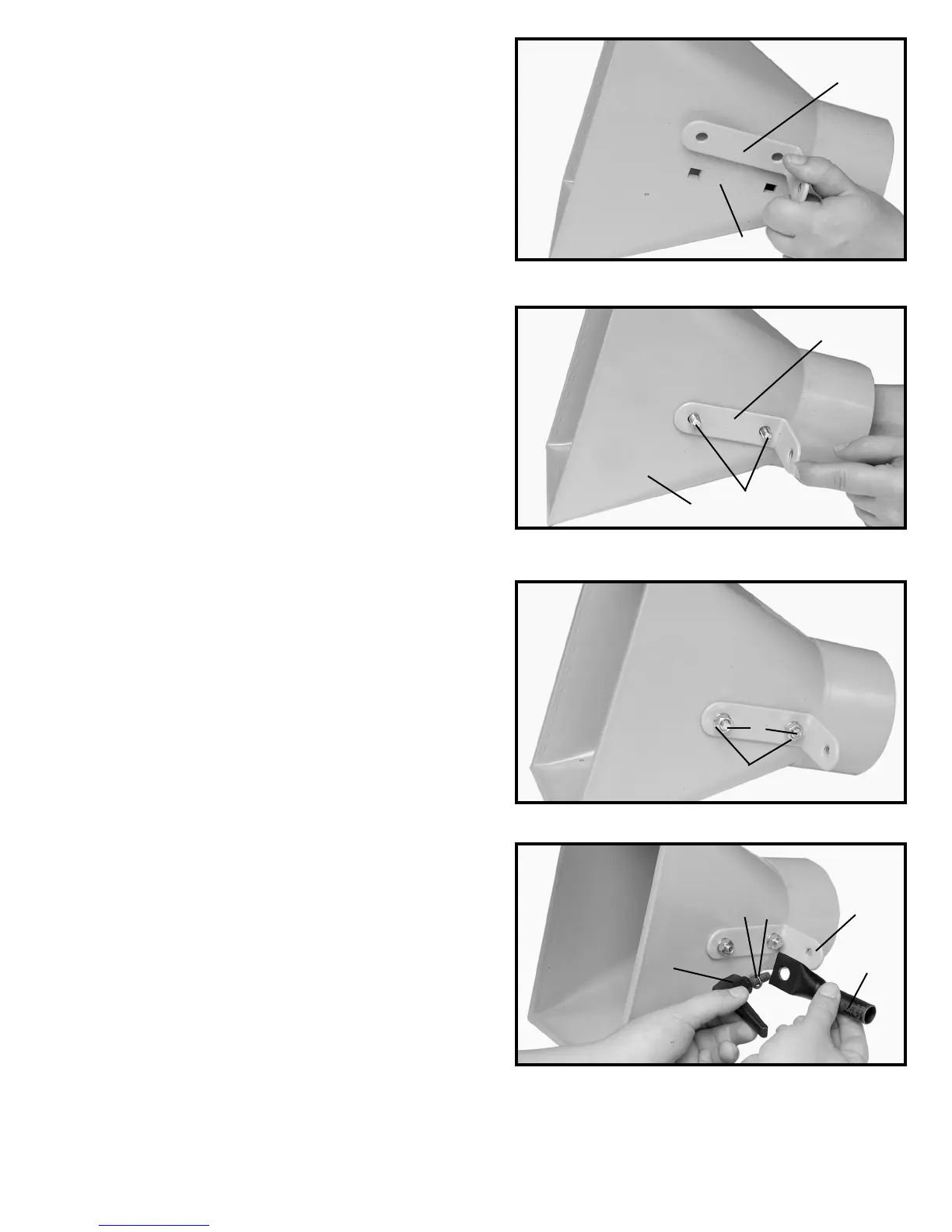
4. Align the two holes in the intake support angle brace
(A) Fig. 10 with the two holes in the intake funnel (B).
5. Fasten the intake support angle brace to the intake
funnel by inserting the two 5/16-18x5/8" button
head carriage bolts (C) thru the intake funnel (B) and
the intake support angle brace (A) as shown in Fig.
11.
6. Thread a 5/16-18" flange hex nut (C) Fig. 12 onto
the bolt (B) and tighten securely.
7. Attach the upper support bracket (B) Fig. 13 to the
intake support angle brace (C) with the adjustable
locking lever (D). NOTE: PLACE A M8.4 FLAT
WASHER (E) AND A 5/16” LOCKWASHER (F) FIG.
13, ONTO LOCKING LEVER SCREW BEFORE
ATTACHING TO THE INTAKE SUPPORT ANGLE
BRACE.
Fig. 10
A
B
Fig. 11
B
A
C
Fig. 12
B
C
Fig. 13
B
C
D
E
F