10
ATTACHING MOTOR AND BLOWER
ASSEMBLY TO FRAME
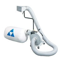
1. Place motor assembly and base assembly on their
side.
2. Align the four holes, two shown at (C), on the top of
the side supports (A) Fig. 8, with the four holes in the
motor assembly (B).
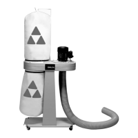
3. Place a 5/16" lockwasher onto a 5/16-18x3/4" hex
head screw and insert the bolt thru the side support
and thread bolt into the tapped hole in the motor
assembly and tighten securely.
4. Repeat this process for the three remaining holes.
5. Fig. 9 shows the motor and blower assembly
attached to the side supports.
Fig. 8
A
A
B
C
SIDE SUPPORTS
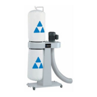
1. Place the dust collector base (A) Fig. 5, in an upright
position as shown.
2. Align the two holes in the wider end of the side
support (B) Fig. 5 with the two holes (C) in the
base.
3. Insert a 5/16-18x3/4" hex head screw (A) Fig. 6 thru
each hole in the side support and base.
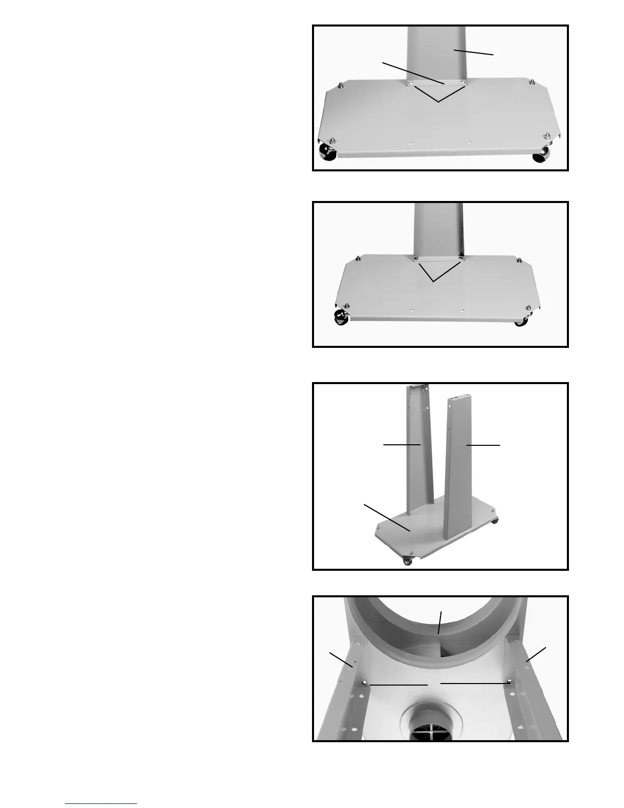
4. Place a 5/16" lockwasher onto the hex head screw.
5. Thread a 5/16-18 hex nut onto the hex head screw
and tighten securely.
6. Repeat this process for the remaining side support.
7. Fig. 7 shows both side supports (A) attached to the
base (B).
Fig. 5
Fig. 6
Fig. 7
B
C
A
A
A
B
A