EasyManua.ls Logo

Delta DFM-400P User Manual

Delta DFM-400P
14 pages
To Next Page IconTo Next Page
Page #1 background imageLoading...
Page #1 background image
Installation & Application Guide
Delta Field Module (4 Pulse Inputs)
DFM-400P (Rev 1.2)
Document Edition 1.6
Product Description
The Delta Field Modules are small expansion I/O boards
that provide remotely expandable I/O to Delta’s BACnet
Controllers. The DFM-400P Pulse Input Field Module
provides four pulsed inputs and communicates directly on
a BACnet RS-485 MS/TP network where it functions as an
independent BACnet device and the pulse counter values
and PI objects are accessible over the MS/TP network.
Ideal for electrical, water, gas, and various flow meters,
the DFM-400P has four pulse inputs. Two inputs support
pulses from 0 to 200 Hz and the other two inputs support
pulses from 0 to 2000 Hz.
Any additional strategies associated with the pulse
counter values are typically programmed in GCL in other
controllers on the network.
Contents
Model Numbers.......................................................................................................................... 2
Package Contents ...................................................................................................................... 2
Other Relevant Documents ........................................................................................................ 2
Important Information ............................................................................................................... 2
Product Specifications ............................................................................................................... 3
Board Layout (DFM-400P) .......................................................................................................... 4
Device Address DIP Switches .................................................................................................... 5
Indicators ................................................................................................................................... 5
Jumpers ..................................................................................................................................... 5
Mounting .................................................................................................................................... 7
Input Wiring ................................................................................................................................ 7
Power ......................................................................................................................................... 7
Network & Cabling Requirements ............................................................................................. 7
Network Topology ...................................................................................................................... 8
Network Communications Setup ............................................................................................... 8
Application Notes ....................................................................................................................... 9
Cautions and Warnings ............................................................................................................ 13
Compliance Declarations ......................................................................................................... 13
Question and Answer IconNeed help?

Do you have a question about the Delta DFM-400P and is the answer not in the manual?

Delta DFM-400P Specifications

General IconGeneral
BrandDelta
ModelDFM-400P
CategoryControl Unit
LanguageEnglish

Summary

Product Description

Model Numbers

Package Contents

Other Relevant Documents

Important Information

Product Specifications

Power Requirements

Details on the electrical power needs, including voltage, VA, and class.

Ambient Ratings

Specifies the acceptable operating temperature and humidity ranges.

Communication Ports

Details on the NET1 RS-485 LAN, autobaud speeds, and service port.

Inputs

Describes the four pulse inputs, their frequency ranges, and monitoring capabilities.

Technology

Information about the processor, clock, and status indicators.

Device Addressing

Methods for setting the device address via DIP switch or software.

Size

Physical dimensions of the controller and enclosure.

Weight

The weight of the unit including its enclosure.

Board Layout

Indicators

Power Indicator LED

Description of the amber/red LED indicating power status.

CPU Scan Indicator LED

Description of the red LED indicating CPU integrity.

RS-485 Communication Status LEDs

Description of the green/red LEDs for network communication status.

Jumpers

DEBOUNCE Jumper

Enables or disables debounce circuitry for mechanical contacts.

Network Connection Type

Confirms the module is fixed for BACnet MS/TP only, not LINKnet.

Derived Network Addressing (DNA)

DNA Enabled

Device inherits address portions from higher-up devices.

DNA Disabled

Device uses default numbers; useful for multi-vendor installations.

Mounting

Input Wiring

Power

Network & Cabling Requirements

Cabling Specifications

Recommended specifications for BACnet MS/TP twisted shielded pair cable.

Topology

Ensures cable is installed as a daisy-chain for BACnet MS/TP networks.

Maximum Nodes per Network

Defines the maximum number of devices per MS/TP network segment.

Termination Boards

Requirement for termination boards at each end of MS/TP network segments.

Repeater Usage

When a repeater (RPT-768) is necessary for network extension or node count.

Network Topology

MS/TP Subnet Devices Configuration

Modules must reside on the MS/TP network at the Subnet level.

LINKnet Devices Configuration

Not applicable for DFM-400P; it connects only via BACnet RS-485 MS/TP.

Network Communications Setup

Objects

Object Notes

Object Name Properties

Details on character limits for Device, Pulse Input, and AV object names.

PI Object Details

Notes on Description Tab, Pulse Duration, and COV support for PI objects.

AV Object Mapping

AV objects map to PI properties for multi-vendor integration and COV support.

Operation

Time Clock

Explains the module's on-board software clock and time synchronization.

Counting Pulses

Pulse Input Counter Registers

Details on the two sets of counting registers, counter types, and max rates.

Pulse Rate Considerations

Guidance on pulse rate, sample interval, and preventing overflows.

Reset Operations

Reset Command Functionality

Resets counting properties to 0, including total pulses.

Sample Interval Change Effect

Resets other properties to 0 when the sample interval changes.

Programming

MS/TP Connection Objects

All predefined DFM-400P objects are accessible over the MS/TP network.

GCL Programming

Writing GCL programs to use pulsed input values for control strategies.

Cautions and Warnings

Electrostatic Discharge (ESD) Warning

Warning about ESD sensitivity and the need for proper protection.

Compliance Declarations

FCC Compliance Information

Details on FCC compliance for Class A digital devices and potential interference.

Industry Canada Compliance Statement

Statement regarding Class A digital apparatus meeting Canadian regulations.

UL Compliance Information

Product conformity to UL requirements, including safety precautions.

CE Declaration of Conformity

Manufacturer Information

Manufacturer's name and address.

Product Identification

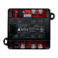
Product name and model numbers.

EMC Compliance

Conformity to Generic Emission and Immunity Standards (EN50081, EN50082).

Supplementary Information

Product compliance with EMC Directive and testing configuration.

Related product manuals