2. Programming Concepts
14. Example 1: Connect 1 Master and 2 Slaves by RS-485 and exchange 16 data between Master
and Slaves through PLC LINK
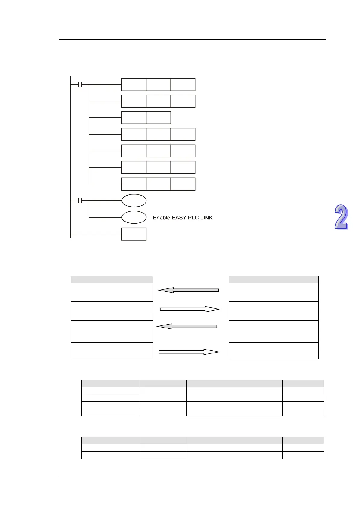
a) Write the ladder diagram program into Master PLC (ID#17)
M1002
MOV K17 D1121
H86 D1120
K16
K16
M1351
END
MOV
SET M1120
MOV
MOV
D1434
D1450
M1350
X1
K16
K16
MOV
MOV
D1435
D1451
Master ID#
COM2 communication protocol
Retain communication protocol
Data length to be read from Slave ID#1
Data length to be written into Slave ID#1
Data length to be read from Slave ID#2
Data length to be written into Slave ID#2
Auto mode
b) When X1 = On, the data exchange between Master and the two Slaves will be
automatically executed by PLC LINK. The data in D100 ~ D115 in the two Slaves will be
read into D1480 ~ D1495 and D1512 ~ D1527 of the Master, and the data in D1496 ~
D1511 and D1528 ~ D1543 will be written into D200 ~ D215 of the two Slaves.
D1480 ~ D1495
D100 ~ D115 of Connection
ID#1
D1496 ~ D1511
D200 ~ D215 of Connection
ID#1
D1512 ~ D1527
D100 ~ D115 of Connection
ID#2
D1528 ~ D1543
D200 ~ D215 of Connection
ID#2
c) Assume the data in registers for data exchange before enabling PLC LINK (M1350 = OFF)
is as below:
D100 ~ D115 of Connection ID#1
D200 ~ D215 of Connection ID#1
D100 ~ D115 of Connection ID#2
D200 ~ D215 of Connection ID#2
After PLC LINK is enabled (M1350 = ON), the data in registers for data exchange
becomes:
D100 ~ D115 of Connection ID#1
D200 ~ D215 of Connection ID#1