3. Instruction Set
API
Mnemonic Operands Function
D
LD#
Contact Type Logic Operation
Type
OP
Bit Devices Word devices Program Steps
X Y M S K H KnX
KnY
KnM
KnS
T C D E F
LD#: 5 steps
DLD#: 9 steps
EX2/
SS2
SA2/
SE
SX2
EX2/
SS2
SA2/
SE
SX2
EX2/
SS2
SA2/
SE
SX2
Operands:
S
1
: Source device 1 S
2
: Source device 2
Explanations:
1. This instruction conducts logic operation between the content in S
1
and S
2
. If the result is not “0”,
the continuity of the instruction is enabled. If the result is “0”, the continuity of the instruction is
disabled.
LD# (#: &, |, ^) instruction is used for direct connection with Left bus bar.
API No.
=
Operation:
& : Logic “AND” operation, | : Logic “OR” operation, ^ : Logic “XOR” operation
When 32-bit counters (C200 ~ C254) are used in this instruction, make sure to adopt 32-bit
instruction (DLD#). If 16-bit instruction (LD#) is adopted, a “program error” will occur and the
ERROR indicator on the MPU panel will flash.
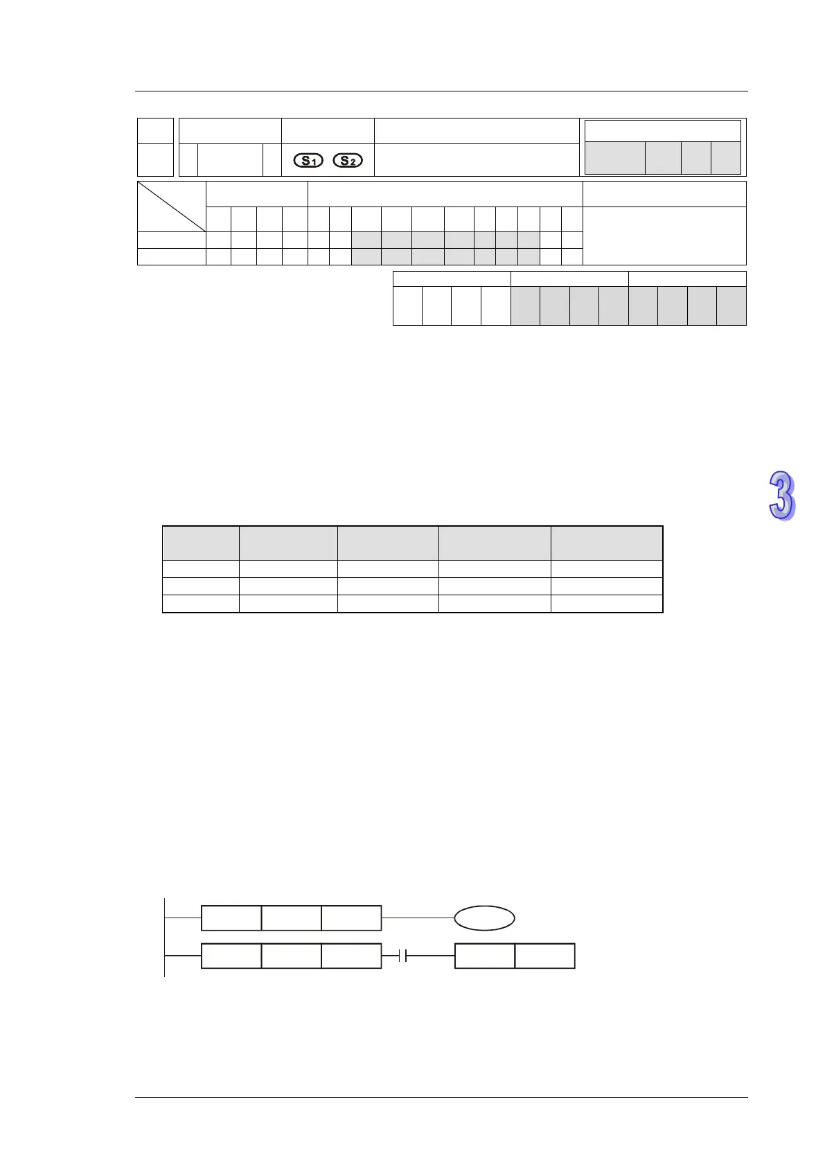
Program Example:
1. When the result of logical AND operation between C0 and C10 ≠ 0, Y20 = ON.
When the result of logical OR operation between D200 and D300 ≠ 0 and X1 = ON, Y21 = ON and
latched.
LD
C0 C10
LD
D200 D300
SET
X1
&
|
Y21
Y20