3. Instruction Set
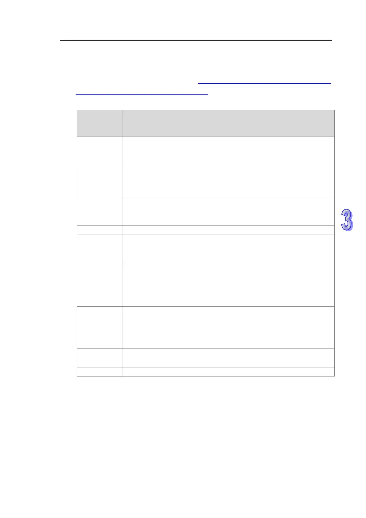
4. InMode sets the input mode of the encoder source and the frequency HYPERLINK
"D:\\Manuals\\DVP\\
ES2 Operation
Manual-Programming\\Editing\\multiplication"D:\Manuals\DVP\ES2 Operation
Manual-Programming\Editing\multiplication for counting.
See the explanation of InMode value in the following table.
Value
Input Modes
Input mode; set as the following values, otherwise the module will use the
16#0000
Fourfold frequency A/B phase input (default).
Phase A leads phase B, indicating counting in the positive direction.
Phase B leads phase A, indicating counting in the negative direction.
16#0001
Onefold frequency A/B phase input.
Phase A leads phase B, indicating counting in the positive direction.
Phase B leads phase A, indicating counting in the negative direction.
16#0002
Twofold frequency A/B phase input.
Phase A leads phase B, indicating counting in the positive direction.
Phase B leads phase A, indicating counting in the negative direction.
16#0004
Fourfold frequency A/B phase input
Phase A leads phase B, indicating counting in the positive direction.
Phase B leads phase A, indicating counting in the negative direction.
16#0005
Pulse + directional input (A+/A-: pulse input; B+/B-: directional input)
Phase B ON: counting in the negative direction
Phase B OFF: counting in the positive direction
Phase A: counting is started by rising-edge trigger.
16#0006
Pulse + directional input (A+/A-: pulse input; B+/B-: directional input)
Phase B ON: counting in the positive direction
Phase B OFF: counting in the negative direction
Phase A: counting is started by rising-edge trigger.
16#0007
Single phase pulse input (A+/A-: pulse input)
Phase A: counting is started by rising-edge trigger.
5. InPulse displays the number of already input pulses, which is a signed 32-bit value. Every
time the instruction is started, the PU module will automatically clear the value to 0 and then
starts counting.
6. InSpeed displays the already detected input frequency which is a 32-bit value. The basic time
for the frequency detection is 20ms. Therefore, the detected input frequency is 0 if there is no
counting value within 20ms. If there is a counting value within 20ms, the output starts at the
minimum frequency of 50Hz. Even if OSpeed value is lower than 50Hz through the
 Loading...