5. Sequential Function Chart
Other Points to Note:
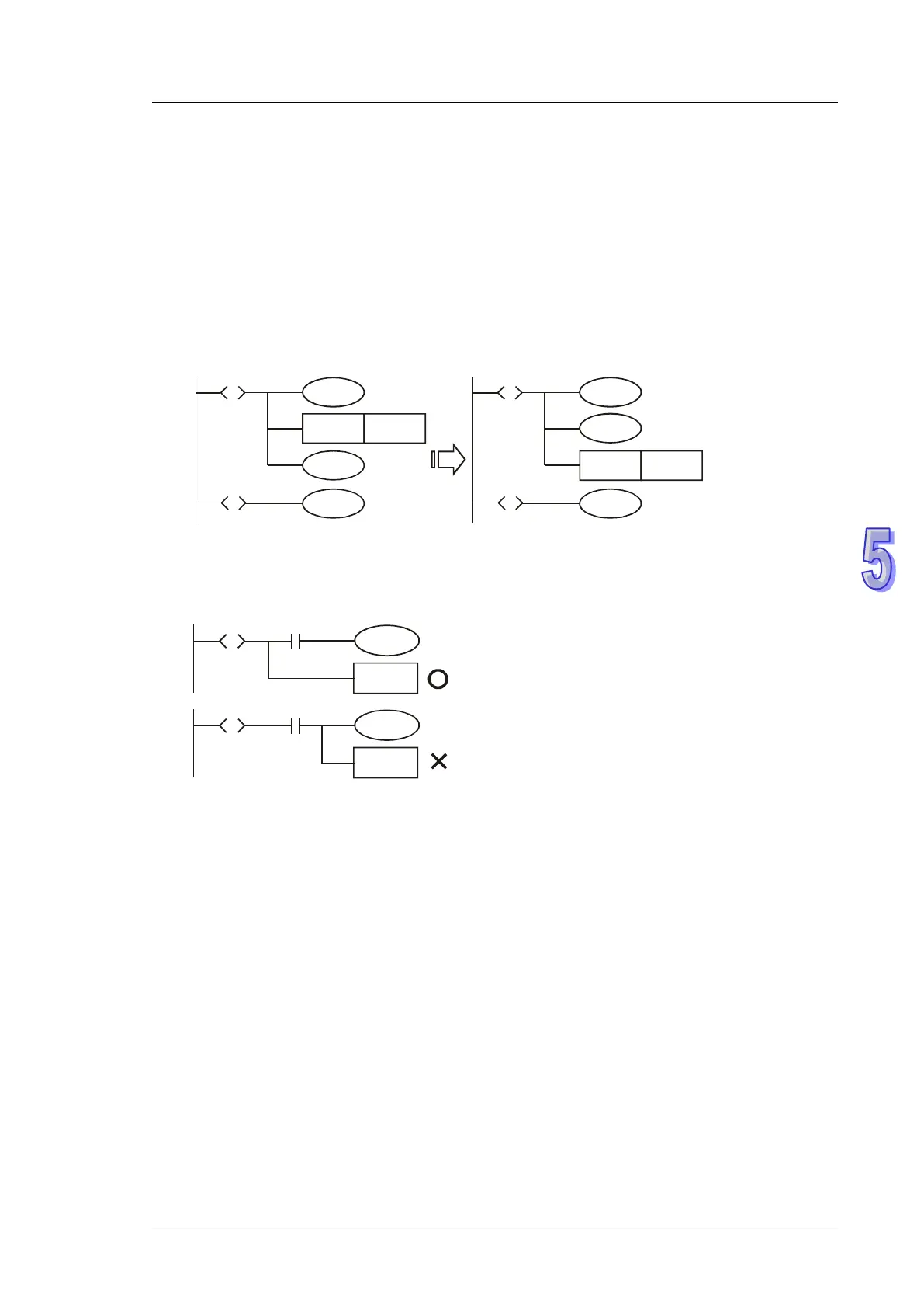
1. The instruction used for transferring the step (SET S□ or OUT S□) are suggested to be
executed after all the relevant outputs and actions in the current step are completed.
The execution results by the PLC are the same. However, if there are many conditions or
actions in S10, it is recommended to modify the diagram in the left into the diagram in the right,
which executes SET S20 after all actions are completed. The sequence will be more
understandable and clear with this modification.
SET
Y0
S10
S
S20
S
Y2
S20
Y1
SET
Y0
S10
S
S20
S
Y2
S20
Y1
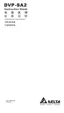
2. As indicated in the below diagram, make sure to connect RET instruction directly after the step
point rather than the NO or NC contact.