- 4 -
CR# Attrib. Register name Explanation
#20 X R Average temp. measured at CH2
CH1~CH8.
The average temperature measured at
CH1~CH8 obtained from the average
time settings in CR#10 ~ CR#17.
#21 X R Average temp. measured at CH3
#22 X R Average temp. measured at CH4
#23 X R Average temp. measured at CH5
#24 X R Average temp. measured at CH6
#25 X R Average temp. measured at CH7
#26 X R Average temp. measured at CH8
#27 O R/W OFFSET value of CH1
Adjustable OFFSET settings at CH1 ~
CH8
Range: -1,000 ~ +1,000
Default = K0
Unit: 0.1°C
Definition of OFFSET value: Module
measurement value – OFFSET value =
actual display value
#28 O R/W OFFSET value of CH2
#29 O R/W OFFSET value of CH3
#30 O R/W OFFSET value of CH4
#31 O R/W OFFSET value of CH5
#32 O R/W OFFSET value of CH6
#33 O R/W OFFSET value of CH7
#34 O R/W OFFSET value of CH8
#35 O R/W Communication address setting
For setting RS-485 communication
address. Range: 01 ~ 254, Default = K1.
#36 O R/W
Communication speed (baud
rate) setting
For setting up communication speed:
9,600/19,200/ 38,400/57,600/115,200
bps. ASCII data format: 7-bit, even bit,
1 stop bit (7, E, 1). RTU data format:
8-bit, even bit, 1 stop bit (8, E, 1).
Default: H’0002.
b0: reserved
b1: 9,600 bps (default).
b2: 19,200 bps.
b3: 38,400 bps.
b4: 57,600 bps.
b5: 115,200 bps.
b14: High/low bit exchange of CRC
checksum (only valid in RTU
mode)
b15: Switch between ASCII/RTU
modes; 0 = ASCII mode (default)
#37 X R Error status
Register for storing all error status. See
the table of error status for more
information.
#38~47 X R Reserved
-
Symbols: O: Latched. X: Non-latched.
R: Able to read data by FROM instruction or RS-485 communication.
W: Able to write data by TO instruction or RS-485 communication.
※ The corresponding parameter address H’4200 ~ H’4232 are for users to read/write
data by RS-485 communication. When using RS-485, the user has to separate the
module with MPU first.
1.
Function: H’03 (read register data); H’06 (write 1 word datum into register); H’10
(write many word data into register).
2.
Latched CR should be written by RS-485 communication to stay latched. CR will
not be latched if written by MPU through TO/DTO instruction.
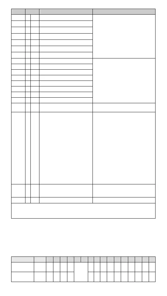
CR#37:
Error status (see the table below)
Error status Value
b15 b14 b13 b12 b11 b10 b9 b8 b7 b6 b5 b4 b3 b2 b1 b0
Abnormal
power supply
K1
(H’1)
00 00
Reserved
0 0 0 0 0 0 0 0 0 1
Abnormal
module
K2
(H’2)
00 00 000000 0 0 1 0
 Loading...