DVP-ES2/EX2/EC5/SS2/SA2/SX2/SE&TP Operation Manual - Programming
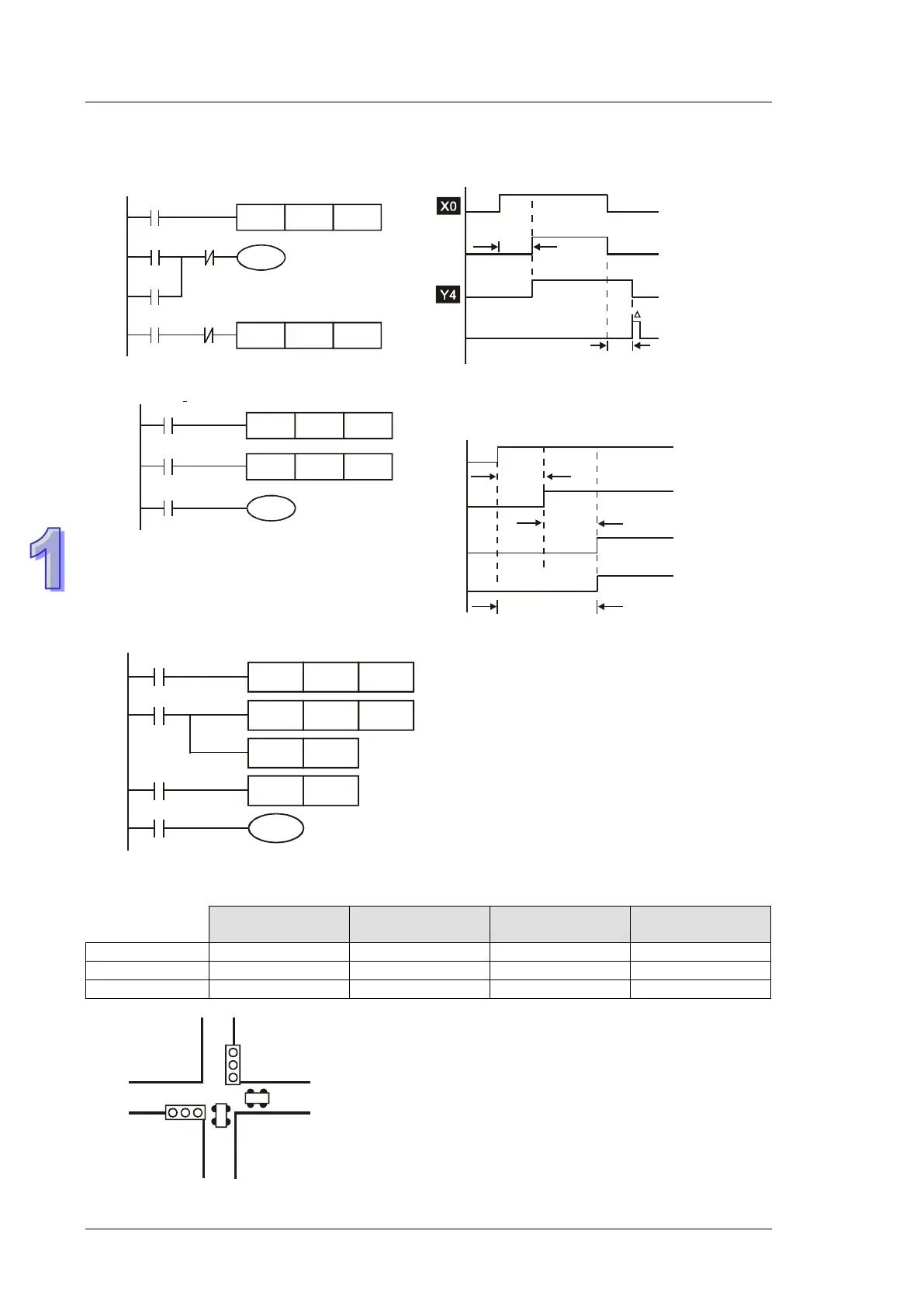
Example 13 - Output delay circuit
The output delay circuit is composed of two timers executing delay actions. No matter input X0 is
ON or OFF, output Y4 will be delayed.
T5
T5
TMR
Y4
T6
X0
K50
Y4
T6
Y4
TMR
X0
K30
Example 14 - Timing extension circuit
.
T12
TMR Kn2
T11
X0
TMR
Y1
T11
Kn1
T12
Timer = T11, T12
Timer resolution: T
The total delay time: (n1+n2)* T. T refers to the
timer resolution.
X0
Y1
T11
T1
2
n1*
n2*
T
T
(n1+n2)*
T
Example 15 – Counting Range Extension Circuit
C6
CNT Kn2
C5
X13
CNT
RST
C5
Kn1
X14
C5
RST
Y1
C6
C6
The counting range of a 16-bit counter is 0 ~
32,767. The opposite circuit uses two counters to
increase the counting range as n1*n2. When
value in counter C6 reaches n2, The pulses
counted from X13 will be n1*n2.
Example 16 - Traffic light control (Step Ladder Logic)
Traffic light control
Red light Yellow light Green light
Vertical
Light
Horizontal
Light