- 2 -
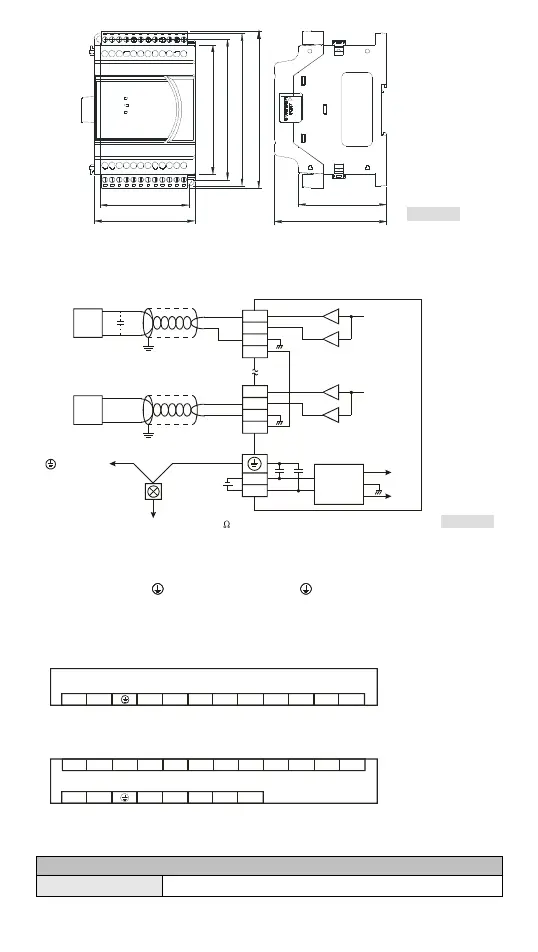
[ Figure 2 ]
70
62
106
98
78
90
61.5
110
Unit: mm
External Wiring
VO1
IO1
AG
VO4
IO4
AG
0V
24V
DC/DC
+15V
-15V
AG
FE
FE
CH1
CH1
Isolation wire*1
-10V~+10V
*2
*3
0mA~20mA
DC24V
CH4
CH4
[ Figure 3 ]
Voltage output
AC drive, recorder,
scale value...
AC drive, recorder,
scale value...
Current output
Isolation wire*1
Te rm in a l o f
power module
System
grounding
Class 3 grounding (100 or less)
converter
Note 1: Please isolate analog output and other power wiring.
Note 2: If noise interferes from loaded input wiring terminal is significant, please connect a capacitor
with 0.1 ~ 0.47μF 25V for noise filtering.
Note 3: Please connect
power module terminal and analog output module terminal to system
earth point and make system earth point be grounded or connects to machine cover.
I/O Terminal Layout
DVP02DA-E2
FEFEFE0V24V
DVP02DA-E2 (2AO)
AGIO2VO2AGIO1VO1
12 3 4
5
678 9
10 11 12
DVP04DA-E2
12 3 4
5
678 9
1
1
12
IO4VO4FE
0V
24V
DVP04DA-E2 (4AO)
FEAG
IO2VO2FEAGIO1VO1
FEAGIO3VO3FEAG
12
3
4
5678
Electrical Specifications
Digital/Analog module (02D/A & 04D/A)
Power supply voltage 24VDC (20.4VDC ~ 28.8VDC) (-15% ~ +20%)