- 4 -
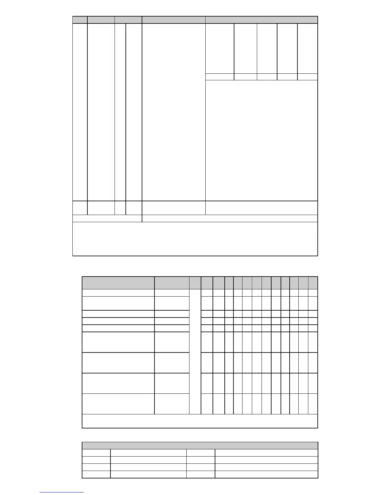
CR# Address Save Register content Description
b15~b12 b11~ b9 b8~b6 b5~b3 b2~b0
ERR LED CH4 CH3 CH2 CH1
#33 H’4085 O R/W
Reset to default
setting
Example: Setting of CH1
1. b0 ~ b1: Reserved.
2. b2: Set to 1 and PLC will be reset to
default settings.
Definition of ERR LED: b12~b15=1111
(default settings)
1. b12 corresponds to CH1: when
b12=1, scale exceeds the range, ERR
LED flashes.
2. b13 corresponds to CH2: when
b13=1, scale exceeds the range, ERR
LED flashes.
3. b14 corresponds to CH3: when
b14=1, scale exceeds the range, ERR
LED flashes.
4. b15 corresponds to CH4: when
b15=1, scale exceeds the range, ERR
LED flashes.
#34 H’4086 O R Software version
Display the software version in
hexadecimal. ex: H’010A = version 1.0A
#35 ~ #48 System used
Symbols:
O: means latched. X: means not latched. (Support when using RS-485 communication, not
support when connecting with MPU)
R: able to read data by using FROM instruction or RS-485.
W: able to write data by using TO instruction or RS-485.
1. Function code: 03’H - read data from register. 06’H - write one word to register. 10’H - write
multiple words to registers.
2. CR#30 is the error code register. Refer to the chart below:
Error description Content
b15
b12
b11 b10 b9 b8 b7 b6 b5 b4 b3 b2 b1 b0
Power source abnormal K1 (H’1)
0 0 0 0 0 0 0 0 0 0 0 1
The contact is not
connected to anything.
K2 (H’2)
0 0 0 0 0 0 0 0 0 0 1 0
Hardware malfunction K16 (H’10)
0 0 0 0 0 0 0 1 0 0 0 0
Average times setting error K64 (H’40)
0 0 0 0 0 1 0 0 0 0 0 0
Instruction error K128 (H’80)
0 0 0 0 1 0 0 0 0 0 0 0
The contact of CH1 is not
connected to anything.
(Abnormal conversion)
K256
(H’100)
0 0 0 1 0 0 0 0 0 0 0 0
The contact of CH2 is not
connected to anything.
(Abnormal conversion)
K512
(H’200)
0 0 1 0 0 0 0 0 0 0 0 0
The contact of CH3 is not
connected to anything.
(Abnormal conversion)
K1024
(H’400)
0 1 0 0 0 0 0 0 0 0 0 0
The contact of CH4 is not
connected to anything.
(Abnormal conversion)
K2048
(H’800)
Reserved
1 0 0 0 0 0 0 0 0 0 0 0
Note: Each error code will have corresponding bit (b0 ~ b7). Two or more errors may
happen at the same time. 0 means normal and 1 means having error.
3. When CR#29 is set to H’5678, CR#0 ~ CR#34 can be used for PID settings in DVP04PT-S
V3.08 and versions above.
PID Mode Content Description
CR#0 Model name CR#22 CH4 K
I
CR#2 PID output % at CH1 CR#24 CH1 K
D
CR#3 PID output % at CH2 CR#25 CH2 K
D
CR#4 PID output % at CH3 CR#26 CH3 K
D

 Loading...


