- 4 -
3. Use 1.6mm wire (or longer) for the grounding of the PLC.
4. The power shutdown of less than 10ms will not affect the operation of the PLC.
However, power shutdown time that is too long or the drop of power supply voltage
will stop the running of the PLC, and all outputs will go “OFF”. When the power
returns to normal status, the PLC will automatically resume operation. (Care should
be taken on the latched auxiliary relays and registers inside the PLC when
programming.)
5. The +24V output is rated at 0.5A from MPU. DO NOT connect other external power
supplies to this terminal. Every input terminal requires 5 ~ 7mA to be driven; e.g. the
16-point input will require approximately 100mA. Therefore, +24V terminal cannot
give output to the external load that is more than 400mA.
Safety Wiring
In PLC control system, many devices are controlled at the same time and actions of any
device could influence each other, i.e. breakdown of any device may cause the
breakdown of the entire auto-control system and danger. Therefore, we suggest you
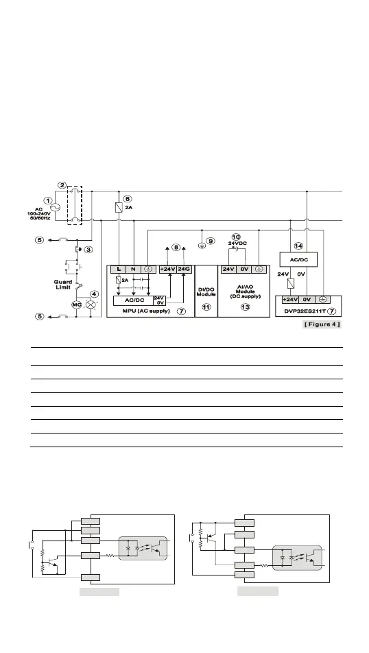
wire a protection circuit at the power supply input terminal. See the figure below.
○
1
AC power supply:100 ~ 240VAC, 50/60Hz
○
2
Breaker
○
3
Emergency stop: This button cuts off the system power supply when accidental
emergency takes place.
○
4
Power indicator
○
5
AC power supply load
○
6
Power supply circuit protection fuse (2A)
○
7
DVP-PLC (main processing unit)
○
8
DC power supply output: 24VDC, 500mA
○
9
Grounding resistance: < 100Ω
○
10
DC power supply: 24VDC
○
11
Digital I/O module (DC supply)
○
12
Digital I/O module (AC supply)
○
13
Analog I/O module (DC supply)
○
14
DC power supply: 20.4VDC~28.8VDC
I/O Point Wiring
There are 2 types of DC inputs, SINK and SOURCE. (See the example below. For
detailed point configuration, please refer to the specification of each model.)
y DC Signal IN – SINK mode
Input point loop equivalent circuit
y DC Signal IN – SOURCE mode
Input point loop equivalent circuit
24G
+24V
S/S
X0
X1
[ Fi gur e 5 ]
+24V
24G
S/S
X0
X1
[ Figure 6 ]
 Loading...


