- 3 -
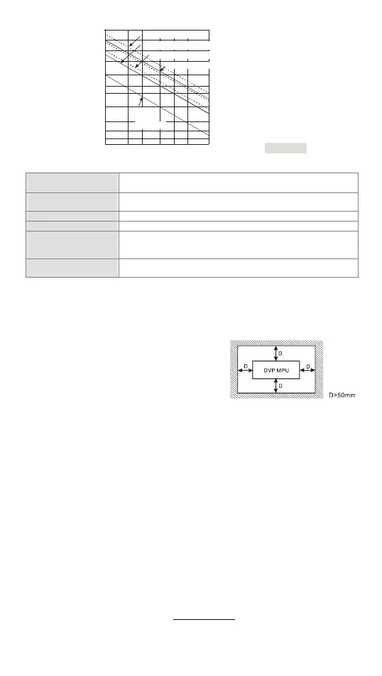
#2: Life curves
Contact
Current(A)
20
0.5
0.1
0.2
30
50
0.3 0.7
12
200
300
500
100
1,000
2,000
3,000
O
p
e
r
a
t
i
o
n
(
X
1
0
)
3
120VAC Resistive
30VDC Inductive(t=7ms)
240VAC Inductive(cos 0.4)ψ=
120VAC Inductive(cos =0.4)ψ
30VDC
Inductive
( t=4 0ms)
[ Figure 3 ]
CANopen Specifications
Communication type
PDO, SDO, SYNC (synchronous transmission), Emergency
(emergency transmission), NMT
Serial communication
speed
Supports 20K、50K、125K、250K、500K、1M bps (bit/second)
Station address 1~127
Electrical isolation 500V DC
Communication cable
Users are suggested to use the Delta standard cable TAP-CB01
or TAP-CB02, and the communication cable should be kept away
from the power cable.
Control flag M1349
ON: (Default) Communication is enabled.
OFF: Communication is disabled.
Note 1: The station addresses of slaves connected to DVP32ES2-C as a master only can range
between 1 and 16. Besides, the station address of the master and that of the slave can
not be the same.
Note 2: The network function of CANopen should be set by means of CANopen Builder. Please
refer to the software manual for more information about the setting.
Installation
Please install the PLC in an enclosure with
sufficient space around it to allow heat dissipation,
as shown in the figure.
y Direct Mounting: Please use M4 screw
according to the dimension of the product.
y DIN Rail Mounting: When mounting the PLC to
35mm DIN rail, be sure to use the retaining clip to stop any side-to-side movement o
the PLC and reduce the chance of wires being loose. The retaining clip is at the
bottom of the PLC. To secure the PLC to DIN rail, pull down the clip, place it onto the
rail and gently push it up. To remove the PLC, pull the retaining clip down with a fla
screwdriver and gently remove the PLC from DIN rail.
Wiring
1. Use the 12-24 AWG single-core bare wire or the multi-core wire for the I/O wiring.
The PLC terminal screws should be tightened to 3.80 kg-cm (3.30 in-lbs) and
please use 60/75°C copper conductor only.
2. DO NOT wire empty terminal. DO NOT place the input signal wire and output
power wire in the same wiring circuit.
3. DO NOT drop tiny metallic conductor into the PLC while screwing and wiring.
y Please attach the dustproof sticker to the PLC before the installation to prevent
conductive objects from dropping in.
y Tear off the sticker before running the PLC to ensure normal heat dissipation.
Power Supply
The power input type for DVP-ES2 model is AC input. When operating DVP-ES2,
please note the following points:
1. The range of the input voltage should be 100 ~ 240VAC. The power supply should
be connected to L and N terminals. Please note that wiring AC110V or AC220V to
+24V output terminal or digital input points will result in serious damage on the PLC.
2. The AC power inputs for the MPU and the digital I/O module should be ON or OFF at
the same time.
 Loading...


