EasyManua.ls Logo

Delta DVP32ES300T User Manual

Delta DVP32ES300T
411 pages
To Next Page IconTo Next Page
To Previous Page IconTo Previous Page
Page #119 background imageLoading...
Page #119 background image
Chapter 5 CPU and Module Devices
5-13
5_
X0. 0
T0(PV)
Y0. 0
SV: K100
10se c
M0
M1
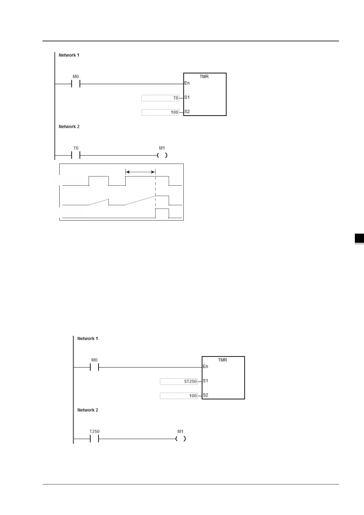
B. Accumulative timers
When the TMR instruction is executed, the accumulative timer begins to count. When the value of the timer matches
the timer setting value, the output coil is ON. As long as you add the letter S in front of the letter T, the timer becomes
an accumulative timer. When the conditional contact is OFF, the value of the accumulative timer is not reset. When
the conditional contact is ON, the accumulative timer counts from the current value.
When M0=ON and the timer T250 takes 100 ms as the timing unit, the output coil T250 is ON when the value
of the timer = timer setting value 100.
When M0=OFF or the power is off, the accumulative timer ST250 stops counting, and the value of the timer
stays the same. When M0=ON, the value of the timer is the accumulating value. When the accumulated value
= timer setting value 100, the output coil T250 is ON.

Table of Contents

Question and Answer IconNeed help?

Do you have a question about the Delta DVP32ES300T and is the answer not in the manual?

Delta DVP32ES300T Specifications

General IconGeneral
ModelDVP32ES300T
I/O Points32
Digital Inputs16
Digital Outputs16
Power Supply24V DC
Communication PortsRS-232, RS-485
Program Capacity16k Steps
Operating Temperature0°C to 55°C
Storage Temperature-25°C to 70°C
Input Type24 VDC Sink/Source
Controller TypeProgrammable Logic Controller
Output TypeTransistor
Dimensions90 x 120 x 90 mm
Humidity5% to 95% RH (non-condensing)

Summary

Chapter 3 Installing Software

3.1 Installing and Uninstalling ISPSoft

Provides steps for installing and uninstalling the ISPSoft software platform for PLC programming and configuration.

Chapter 4 Installing Hardware

4.4 Wiring

Covers essential warnings and notes regarding wiring I/O modules, including cable types and grounding.

Chapter 6 Writing a Program

6.6 Testing and Debugging a Program

Explains how to download programs and parameters to the PLC and use monitoring modes for testing.

Chapter 7 Memory Card

Chapter 8 Hardware Configuration and Data Exchange Setups

8.1 Hardware Configuration Tool for DVP-ES3 Series Modules

Introduces HWCONFIG, the built-in tool for setting CPU and module parameters, and downloading configurations.

Chapter 9 EtherNet/IP Specification and Operation

9.5 Troubleshooting

Lists common error codes for EtherNet/IP and provides solutions for configuration and application errors.

Chapter 10 CANopen Function and Operation

10.5 Troubleshooting

Covers troubleshooting steps for CANopen network issues, including node state display and error codes.

Chapter 12 Troubleshooting

12.2 Troubleshooting for CPU Modules

Details error codes and LED indicators for CPU modules, offering solutions for various fault conditions.

Chapter 13 Data Tracer and Data Logger

Appendix A Installing a USB Driver

A.1 Disable Driver Signature Enforcement

Provides steps to disable driver signature enforcement in Windows 8 and 10 for installing the Delta PLC USB driver.

A.2 Installing the USB Driver for DVP-ES3 Series CPU Module

Details the procedure for installing the USB driver for the DVP-ES3 Series CPU module on Windows 10.

Appendix D Maintenance and Inspection

D.1 Cautions

Lists critical precautions to observe before performing maintenance and inspection to prevent injury or damage.

Related product manuals