Chapter 5 CPU and Module Devices
5-17
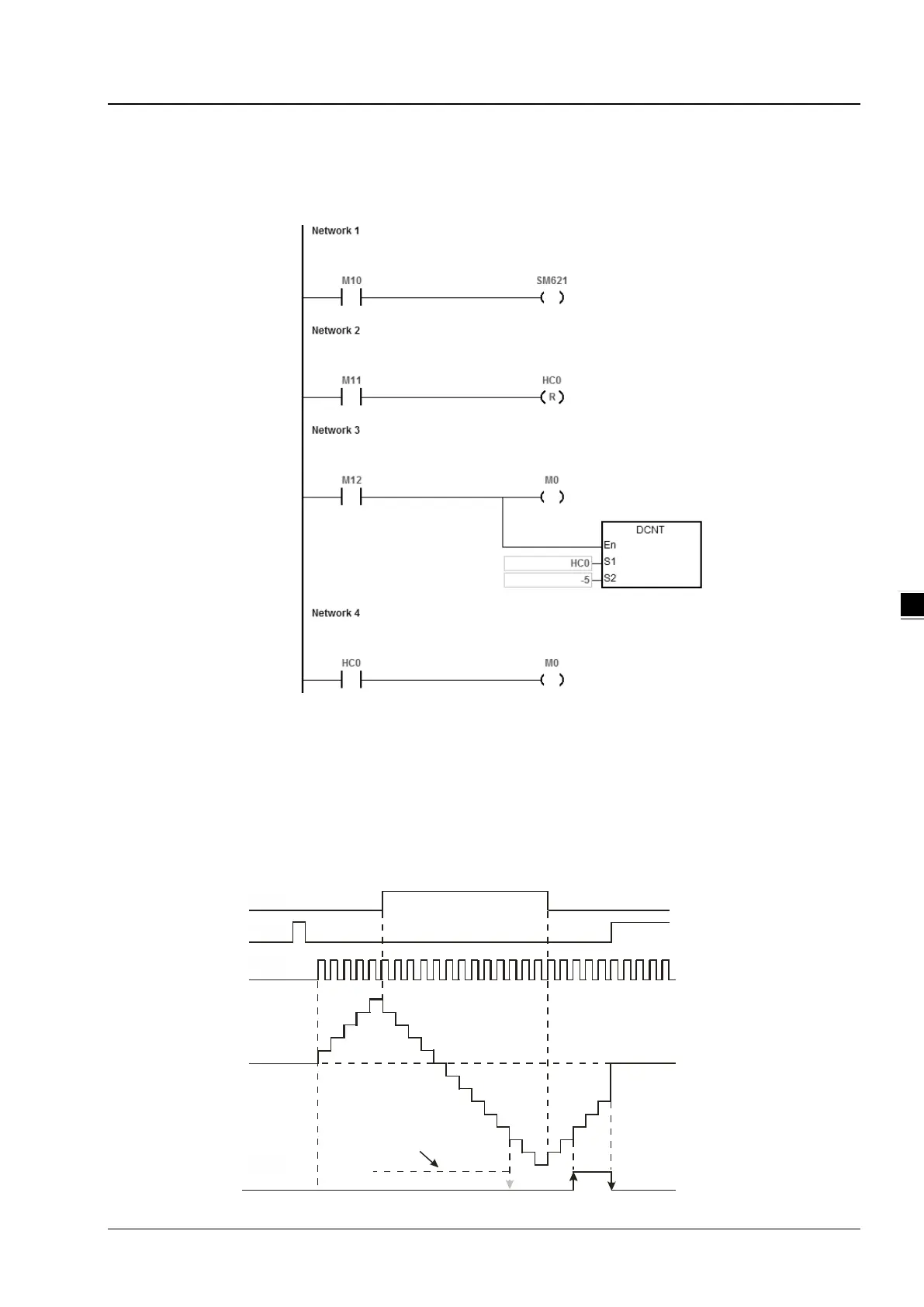
32-bit high speed addition/subtraction counter
Refer to the instruction description of API1004 DCNT in DVP-ES3 Series Programming Manual for more details.
Example:
1. M10 drives SM621 to determine the counting direction (up/down) for HC0.
2. When M11 changes from OFF to ON, the RST instruction is executed and the PV in HC0 is cleared to 0 and its
contact is OFF.
3. When M12 changes from OFF to ON, PV for HC0 will count up (plus 1) or count down (minus 1).
4. When PV in HC0 changes from -6 to -5, the contact HC0 changes from OFF to ON. When PV in HC0 changes from
-5 to -6, the contact HC0 changes from ON to OFF.
X10.0
X11.0
X12.0
When the output contact was ON
Y0.0,
HC0
Contacts
HC0
( )PV
Accumulatively
increasing Progressively
decreasing
0
1
2
3
4
5
4
3
2
1
0
-1
-2
-3
-4
-5
-6
-7
-8
0
-7
-6
-5
-4
-3
Accumulatively
increasing
M10
M11
M12
M0
 Loading...


