EasyManua.ls Logo

Delta DVP32ES300T

Delta DVP32ES300T
411 pages
To Next Page IconTo Next Page
To Previous Page IconTo Previous Page
Loading...
DVP-ES3 Series Operation Manual
10-24
_10
An Emergency 1 consists of the data in D6004-D6007 and every Emergency message consists of 8
bytes of data.
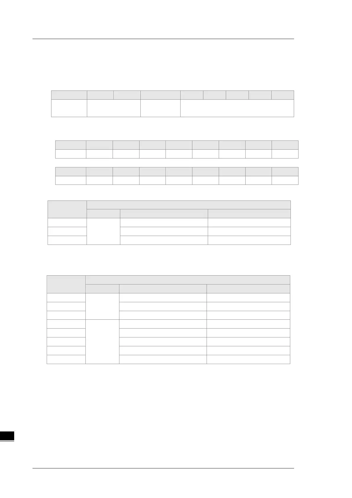
The following table shows the data format of Emergency messages on the CAN bus. Datum 0datum
7 in Emergency response message correspond to byte 0byte 7 respectively.
COB-ID
Byte 0
Byte 1
Byte 2
Byte 3
Byte 4
Byte 5
Byte 6
Byte 7
80 (Hex)
+Node-ID
Emergency error
code
Error storage
register
Vendor custom error code
Example 1: read the Emergency message from the slave No.2, and the Emergency messages the
slave sends out successively.
COB-ID
Byte 0
Byte 1
Byte 2
Byte 3
Byte 4
Byte 5
Byte 6
Byte 7
82 (Hex)
43
54
20
14
0
0
0
0
COB-ID
Byte 0
Byte 1
Byte 2
Byte 3
Byte 4
Byte 5
Byte 6
Byte 7
82 (Hex)
42
54
20
15
0
0
0
0
Request data:
PLC device
Request message
High byte
Low byte
D25000
Message
header
ReqID=01
Command =01
D25001
Reserved
Size =0
D25002
Type =04
Node ID =03
Emergency response data
PLC device
Response message
High byte
Low byte
D24000
Message
header
ResID=01
Status code =01
D24001
Reserved =0
Size =2A (Hex)
D24002
Type =04
Node ID =03
D24003
Message
data
Total number of data =1 Number of data stored =1
D24004
Datum 1=54
Datum 0=42
D24005
Datum 3=20
Datum 2=14
D24006
Datum 5=0
Datum 4=0
D24007
Datum 7=0
Datum 6=0

Table of Contents

Related product manuals