DVP-ES3 Series Operation Manual
4-20
4.6.2.3 Transistor Output Circuit (NPN)
VDC
+
D
ZP
Y
UP
Low power
D: 1N4001 Diode or its equivalent
ZD D
VDC
+
ZP
Y
UP
High power and
ON/OFF frequently
ZD: 9V Zener, 5W
D: 1N4001
Diode or its equivalent
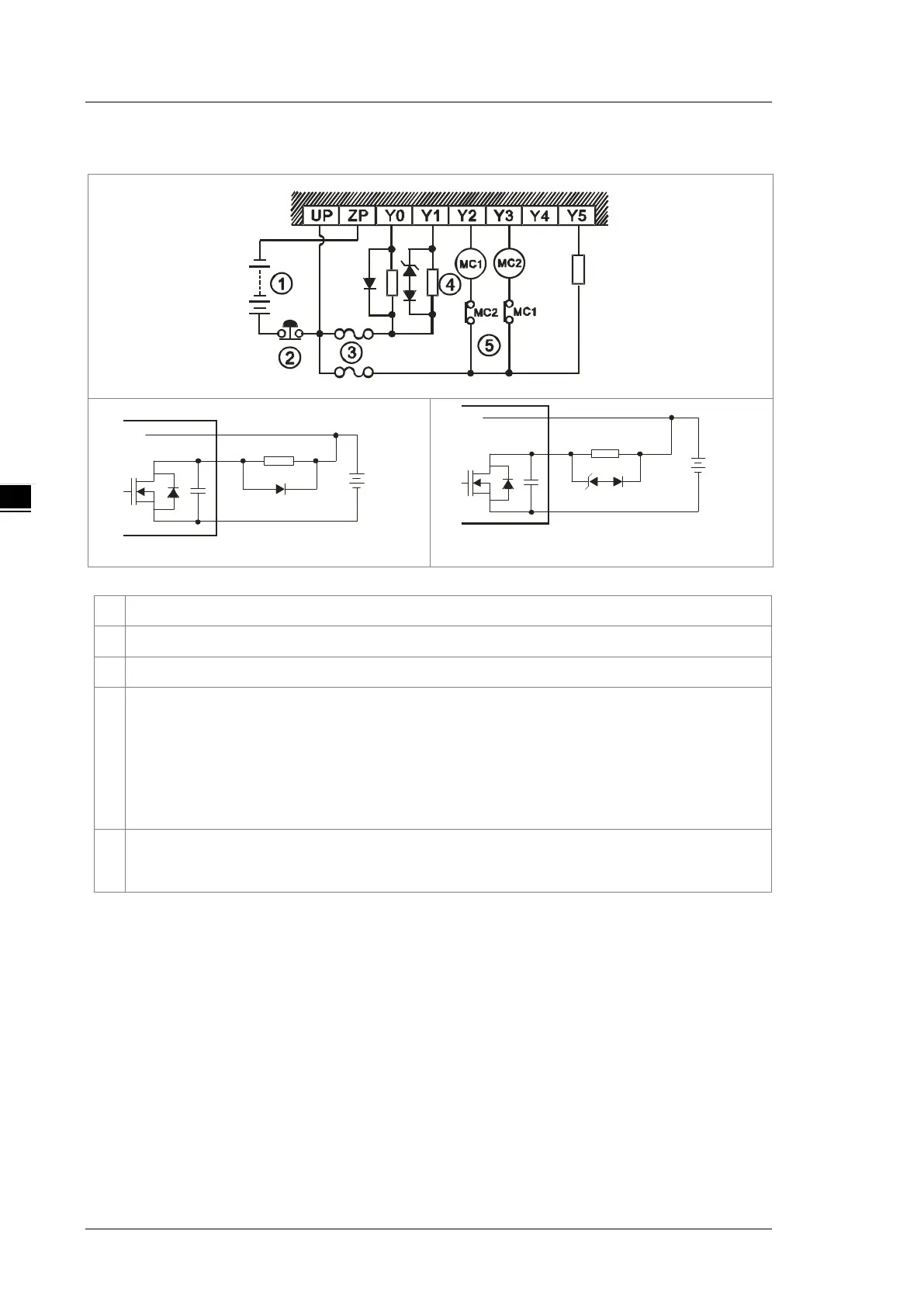
①
Direct-current power supply
②
Emergency stop
③
Fuse
④
The output terminals of a transistor module are open-collector output terminals. If Y0.0/Y0.1 is a pulse
train output terminal of a transistor module, the output current passing through its output pull-
must be greater than 0.1 A to ensure that the transistor module operates normally.
1. A diode is connected in parallel to absorb the surge voltage: used in low-power situations (refer to
Figure 1).
2. A diode and Zener are connected in parallel to absorb the surge voltage: used in high-power and
power-on/off frequently situations (refer to Figure 2).
⑤
Mutually exclusive output: For example, Y2 controls the clockwise rotation of the motor, and Y3 controls
the counterclockwise rotation of the motor. This interlock circuit and the program in the PLC ensure that
there are protective measures if an abnormal condition occurs.
 Loading...


