34
1. Verify that the exposed wires are at least 6 inches in length to provide adequate strain
relief and wire end strip length required.
2. Connect the positive lead from each PV array string to PV_Positive Terminals (A / B / C)
in the wiring box compartment.
3. Connect the negative lead from each PV array string to PV_Negnative Terminals (D / E / F)
in the wiring box compartment.
4. Verify inverter to wiring box compartment connections DC wiring board assembly:
• “RED“ wire goes to “PV_Positive” Terminal
• “BLACK” wire goes to “PV_Negative” Terminal
Note: In E series inverters, if the PV array contains more than 3 PV module strings then
an external PV combiner is recommended.
4.8.5 PV switch LOCK out and TAG out procedure
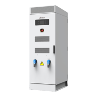
1. Remove power to the System by turning each
operation handle of the DC switch to the [OFF]
Position. Then lockout each circuit breaker as shown
below.
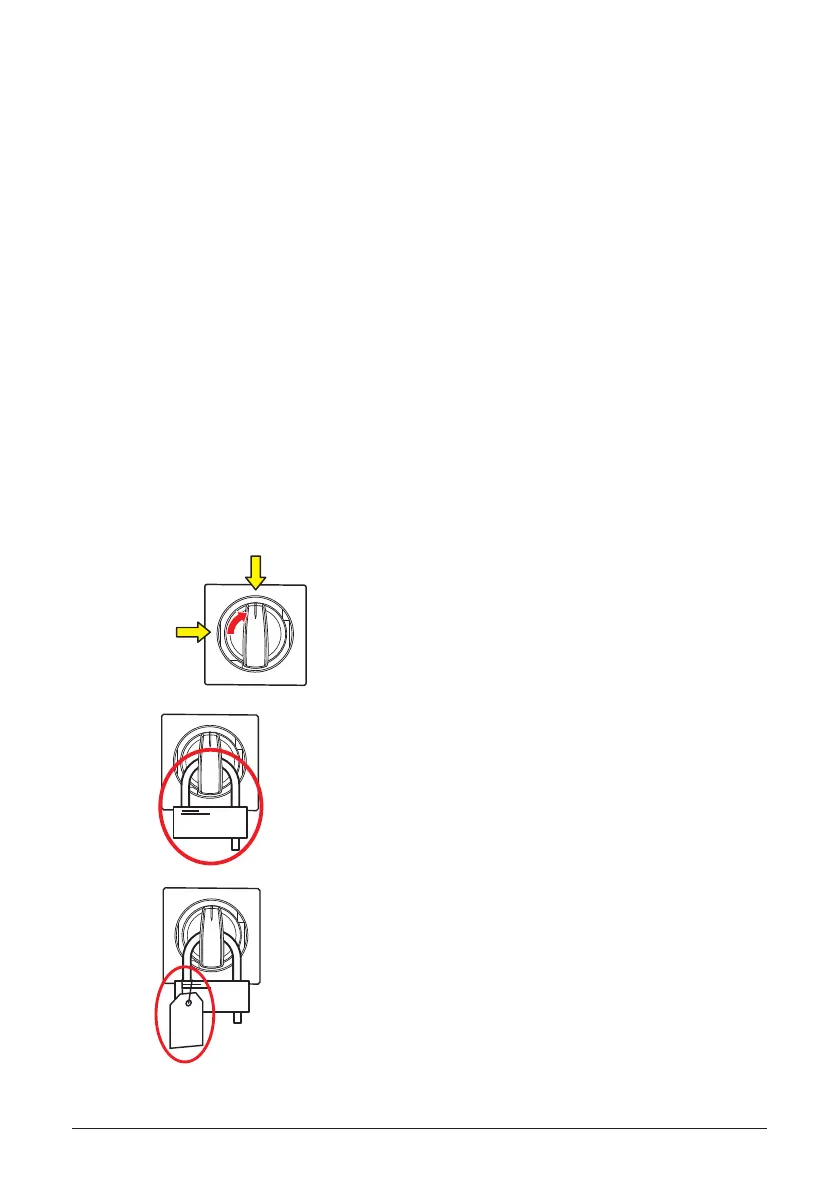
2. Connect the positive lead from each PV array
string tAttach a padlock. After attaching the lock,
attempt to turn the circuit breaker to the ON
position. The lock should prevent the circuit
breaker from being turned on.
3. Attach a tag to the locking plate. The tag
should contain the following information:
WHO locked the circuit breaker out
WHY the circuit breaker is locked out
WHEN the circuit breaker was locked out
The contact information of who locked out
the circuit breaker
ON POSITION
OFF POSITION
 Loading...