39
Interface connection communication
The Delta E series inverters offer an EIA RS485 communication interface which can address up
to 31 daisy chained inverters. In this case, RS485 port 1 and port 2 can only use the pin 7 and
pin 8, that is RS485 TX and RS485 RX
Figure 33: Inverter RS485 system diagram
TERM.
ON
Gateway or Datalogger
INV 1 INV 2
INV 31
RS485
J1
J2
RS485
J1
J2
RS485
J1
J2
J1=RS485 port 1
J2=RS485 port 2
Figure 34: communication ports
CAN and 485 communication ports
Ethernet and 485 communication ports
RGM communication ports
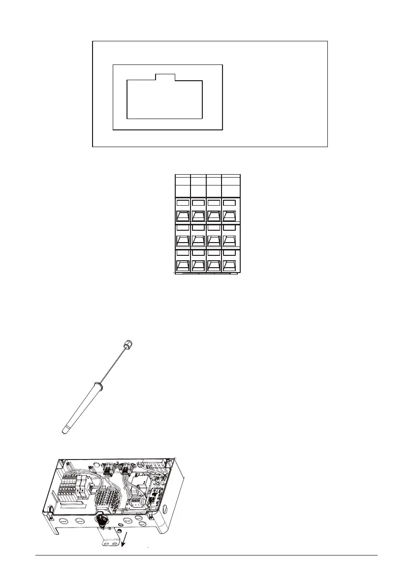
Figure 35:
CAN and 485 communication ports
8
1
Pin
1 ETH_TD+
2 ETH_TD-
3 ETH_RD+
4 RS485 TX
5 RS485 RX
6 ETH_RD-
7 RS485 TX
8 RS485 RX
Top View
Connector pin assignment
1. Take out the antenna. Make sure the sealant
2. ake the cover o with tools.