21
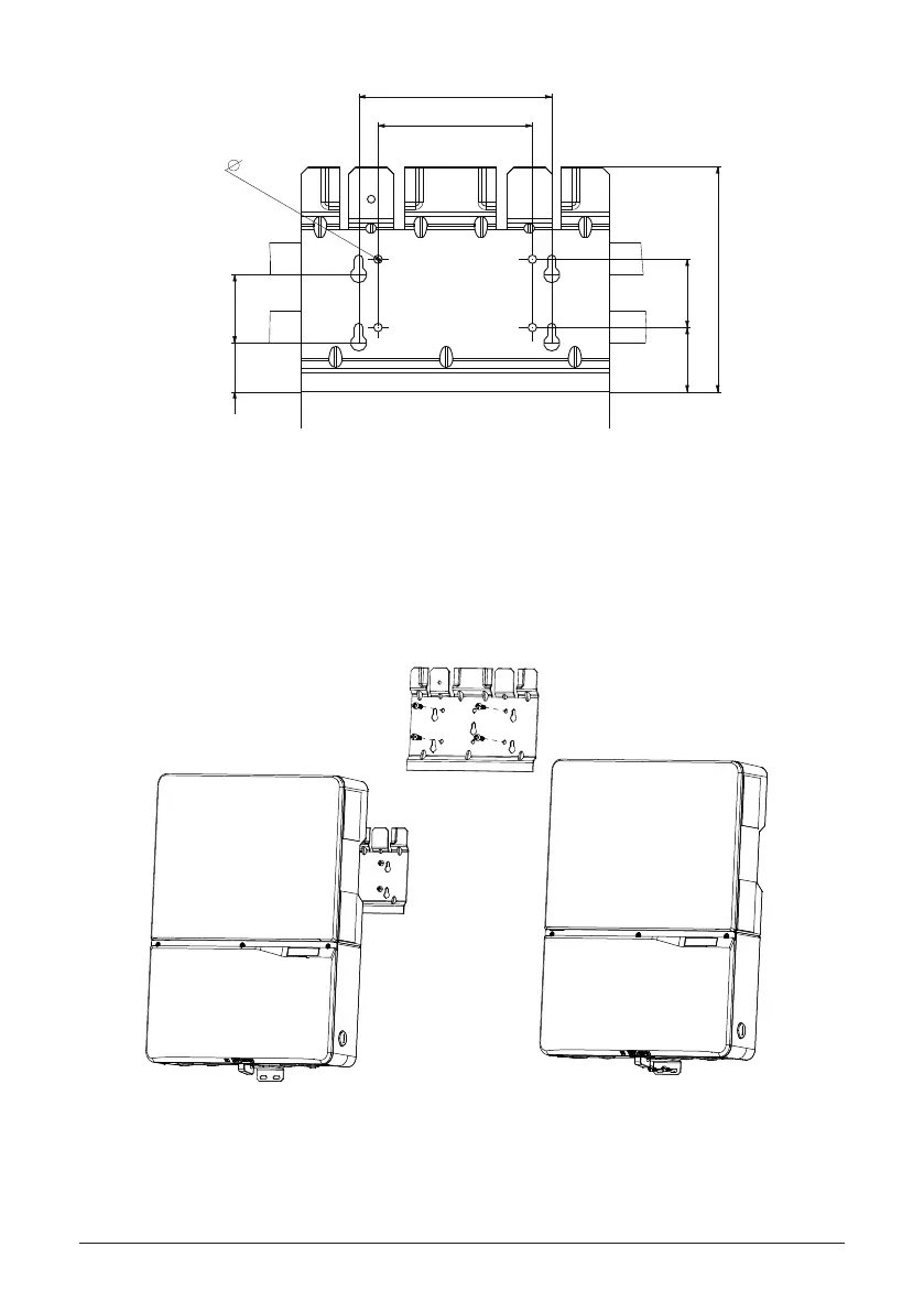
Figure 13: Dimension drawing of mounting plate
1. Mount the mounting plate to the wall with at least 4 screws and anchors (Ø 6mm). With 4
screws use 4 holes A or 4 holes B (see Figure 14). You can use the mounting plate as
a template for marking the positions of the boreholes.
2. Tighten the screws rmly to the wall.
4.72in (120mm)
2.09in
(53mm)
5.91in (150mm)
2.09in
53mm
1.97in
50mm
1.50in
38mm
0.256in
mm6.5
6.88in (174.8mm)
Figure 14: Installing the plate and inverter on a wood stud wall
 Loading...


