30
Venting and Combustion Air Installation
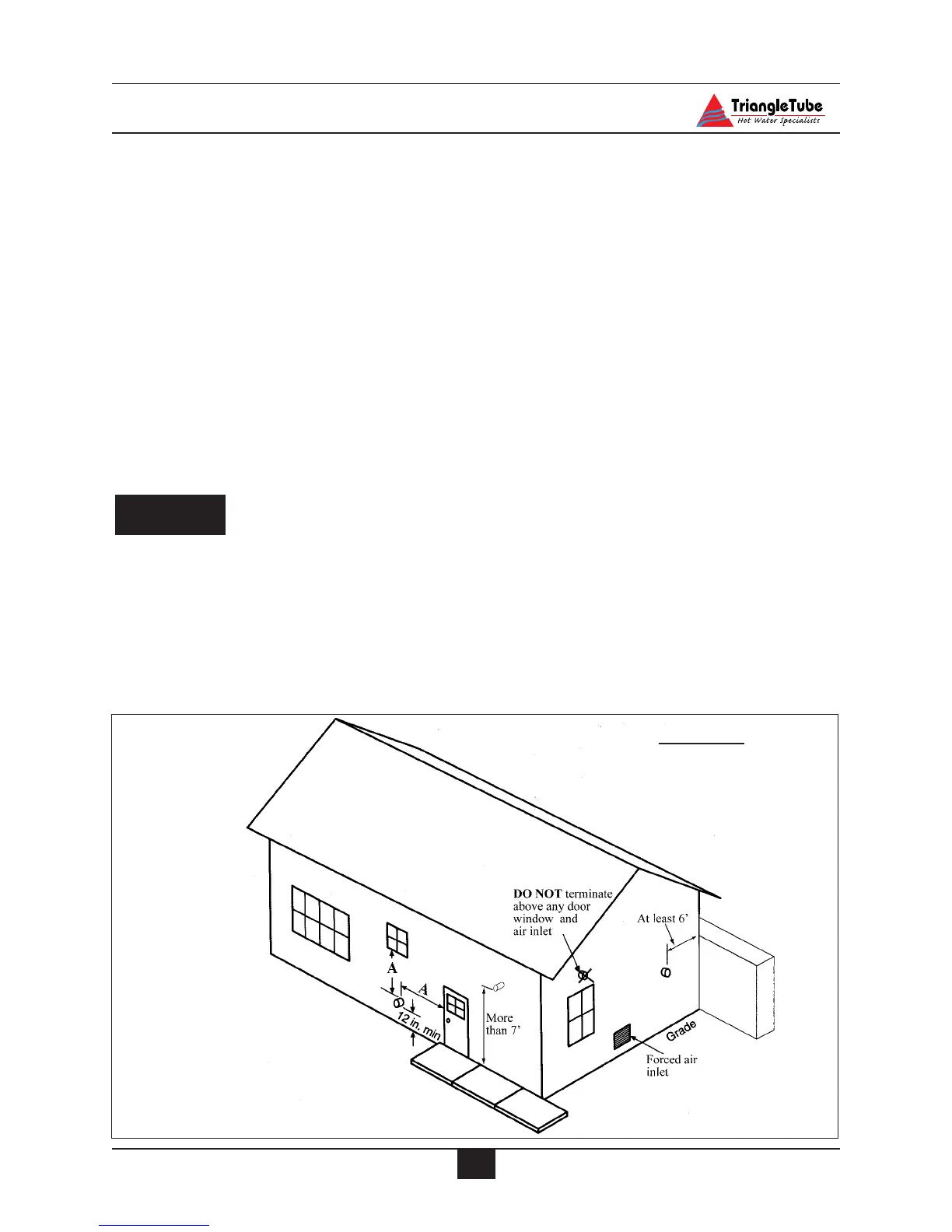
- No closer than 5 feet below roof over-
hangs
- At least 7 feet above any public walk-
ways
- At least 3 feet above any forced air
intake (does not include the combustion
air inlet) within 10 feet.
- The vent termination must be at least 4
feet from any electric meters, gas
meter-regulators, relief valves or other
equipment. Never terminate the vent
above or below any of these items with-
in 4 feet.
-Vent must terminate at least 12 inches
above grade or common snow line.
In those applications in which the vent
termination is below the projected snow
line the installer has 2 options. In the
first option, the vent system can be rout-
ed vertically through an insulated chase
or “riser box” and then terminated hori-
zontally. The chase is to be constructed
and insulated by the contractor, main-
taining clearances for vertical and hori-
zontal enclosures. In the second option
the installer can use the horizontal con-
centric snorkel kit see Fig. 22B page 36.
If the venting application is a horizontal
direct vent:
- Must maintain 12-inch clearances
below and horizontally from doors and
windows. See dimension A Fig. 17.
If the venting application is a horizontal
non-direct vent:
- Must maintain 4 feet of clearance
below and horizontally from doors and
windows. See dimension A Fig. 17.
If the venting application is a vertical direct
or non-direct vent application:
- The vent must terminate at least 3 feet
above the roof and at least 2 feet higher
than any portion of the building within
10 feet.
NOTICE
Fig.17: Termination of Vent system
Dimension A
Direct Vent - 12 inches
Non-Direct Vent - 4 feet