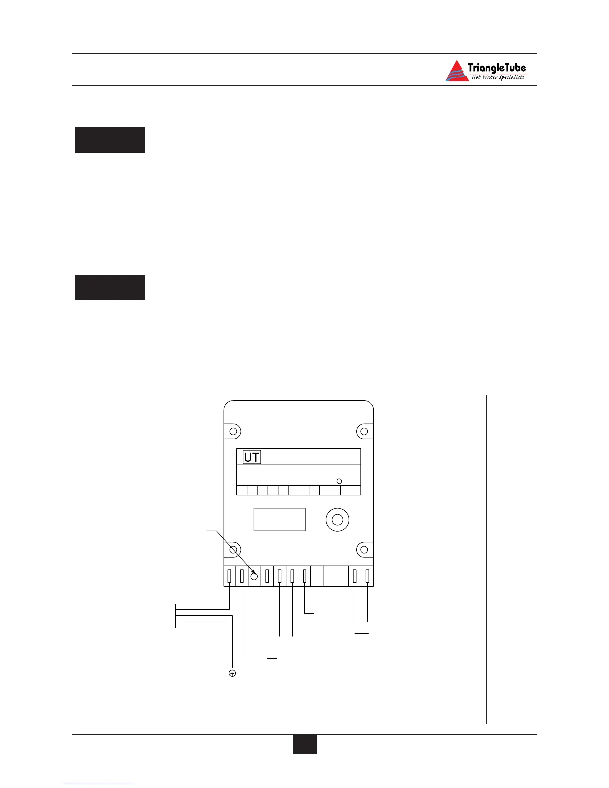
Fig. 29 : Burner Control Wiring
SECTION VIII - Internal Wiring
ELECTRICAL SHOCK HAZARD. For
your safety, disconnect electrical power
supply to the unit before servicing or
making any electrical connections to
avoid possible electric shock hazard.
Failure to do so can cause severe person-
al injury or death.
All electrical contacts shown in Figures
30 & 31 pages 43 & 44 do not have elec-
trical power applied. Shown as “off-
shelf” condition.
General Requirements
-Wiring must be N.E.C Class 1.
- If original wiring installed in the unit
must be replaced, use only type T, 90ºC
wire or equivalent.
- The PERFORMANCE must be electri-
cally grounded as required by National
Electrical Code ANSI/NFPA 70 - latest
edition.
NOTICE
WARNING