- 6 -
1. The power is connected to two terminals, 24 VDC and 0 V, and the range of power is 20.4 to
28.8 VDC. If the power voltage is less than 20.4VDC, TP04P will stop running, all outputs will
be Off, and the ERROR indicator will start to blink.
2. If a power failure lasts for less than 10 ms, the operation of TP04P will not stop. However, if a
power failure lasts for long, or the power voltage decreases, TP04P will stop running, and all
outputs will be off. After the power returns to the normal status, TP04P will automatically
resume the operation. (Users have to note that TP04P is equipped with latched auxiliary
relays and registers when they write a program.)
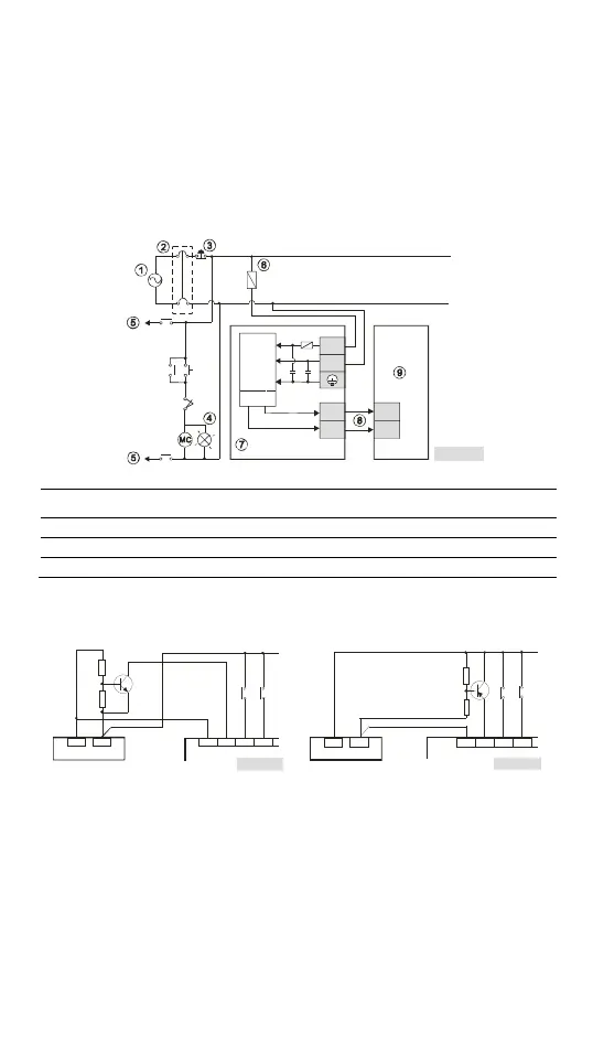
Safety Wiring
Since TP04P is only compatible with DC power supply, Delta’s power supply modules
(DVPPS01/DVPPS02/DVPPS05) are suitable for it. İt is suggested that you shoudl install a
protection circuit at the power supply terminal to protect DVPPS01, DVPPS02, or DVPPS05.
See the figure below.
Fi gu r e 1 0
AC
100- 240 V
50/6 0Hz
Guar d
Limit
DVPPS01/DVPPS02/
DVPPS05
TP 04P
AC/DC
0V 2 4V
L
N
+24V
+24V
0V 0V
2A
2A
AC power supply:100 ~ 240VAC, 50/60Hz
Breaker
Emergency stop: The emergency stop button can be used to cut off the power when an
emergency occurs.
Power indicator
AC power supply load
Power supply circuit protection fuse (2A)
DVPPS01/DVPPS02/DVPPS05
DC power supply output: 24VDC, 500mA
TP04P
Wiring Input Terminals
There are 2 types of DC inputs. They are sinking inputs and souring inputs. (See the
figures below.)
Sinking mode Sourcing mode
+24V OV
Sinking
X1 X2S/S X0
24VDC
Fig ure 11
X1 X2S/S X0+24V OV
24VDC
Sourcing
Fig ure 12
Wiring Relay Output Terminals (Sink)