- 7 -
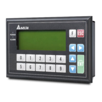
[ F igu re 13 ]
MC2MC1
9
10
C0 C1Y0 Y4C2 Y2 Y3 Y 5Y1
5 2
3 7
8
1
6
7
2
5 4
MC2 MC1
11
DO NOT wire empty
terminal
Fuse
Reverse current
protection diode*1
Manual exclusive
output*2
Emergency stop: by
external switch
Surge absorber*3
Inductive load
Indicator: incandescent
light
DC power supply
AC power supply
11
Resistive load
*1: There is no internal protection circuit in the output relay of the PLC; therefore when activating
an inductive load, we suggest you parallel connect a reverse current protection diode to extend
the life of the contact.
- The diode has to be able to endure max. 5 ~ 10 times of load voltage.
- The positive current of the diode has to be bigger than load current.
*2: Manual exclusive output uses external circuit and forms an interlock, together with the PLC
internal program, to ensure safety protection in case of any unexpected errors.
*3: There is no internal protection circuit in the output relay of the PLC; therefore when activating
an inductive load, we suggest you parallel connect a surge absorber (0.1uF + “100ohm to
120ohm”) to reduce the noise on AC load and extend the life of the contact.
Wiring Transistor Output Terminals (Sink)
[ Figure 14 ]
MC2MC1
C0 C1Y0
Y4
C2
Y2
Y3
Y5
Y1
5 7 8
1
6
6
4
MC2
MC1
2
3
3
9
DO NOT wire empty
terminal
Emergency stop
Fuse
Manual exclusive output*1
DC power supply
Indicator: incandescent light
Reverse current protection
diode*2
Inductive load
Resistive load
*1: Manual exclusive output uses external circuit and forms an interlock, together with the PLC
internal program, to ensure safety protection in case of any unexpected errors.
*2: Use a Zener diode (39V) in the PLC to protect the transistor output. When activating
inductive load, we suggest you parallel connect a reverse current protection diode.
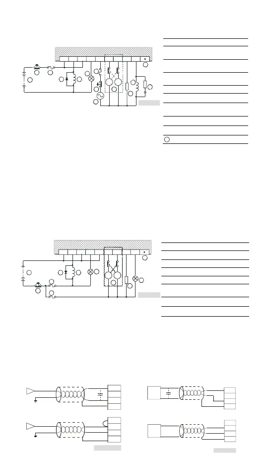
Wiring Analog I/O and Temperature Sensor
TP04P-22XA1R
Analog Input Analog Output
Figu re 15
Shielded
cable*1
Volt a
e in put
Current input
Shielded
cable*1
-10V~+10V
V0+
I0
V0-
CH0
-20mA~+20mA
V3+
I3
V3-
CH3
*3
*2
FE
FE
Figure 16
Vol tag e output
Sh ielded
cable*1
Shielded
cab le*1
Cur rent o utput
A C motor dr i ve, rec o rder,
p ropor tioni ng va lve ...
AC motor d rive, re corder ,
propo rti onin g va l ve...
V5
I5
AG
CH5
0mA ~20 mA
V4
I4
AG
CH4
-1 0V~ +10V
*3
FE
FE