Chapter 7 Optional AccessoriesCP2000
7-6
3. Any damage to the drive or other equipment caused by using brake resistors and brake modules that are not
provided by Delta voids the warranty.
4. Consider environmental safety factors when installing the brake resistors. If you use the minimum resistance
value, consult local dealers for the power calculation.
5. When using more than two brake units, the equivalent resistor value of the parallel brake unit cannot be less
than the value in the column “Minimum Resistor Value (Ω)”. Read the wiring information in the brake unit
instruction sheet thoroughly prior to operation. Visit the following links to get the instruction sheets for the
wiring in the brake unit:
VFDB2015 / 2022 / 4030 / 4045 / 5055 Braking Modules Instruction Sheet
http://www.deltaww.com/filecenter/Products/download/06/060101/Option/DELTA_IA-MDS_VFDB_I_EN_
20070719.pdf
VFDB4110 / 4160 / 4185 Braking Modules Instruction Sheet
http://www.deltaww.com/filecenter/Products/download/06/060101/Option/DELTA_IA-MDS_VFDB4110-41
60-4185_I_EN_20101011.pdf
VFDB6055 / 6110 / 6160 / 6200 Braking Modules Instruction Sheet
http://www.deltaww.com/filecenter/Products/download/06/060101/Option/DELTA_IA-MDS_VFDB6055-61
10-6160-6200_I_TSE_20121030.pdf
6. This chart is for normal usage; if the AC motor drive is applied for frequent braking, it is suggested to enlarge
2–3 times of the Watts.
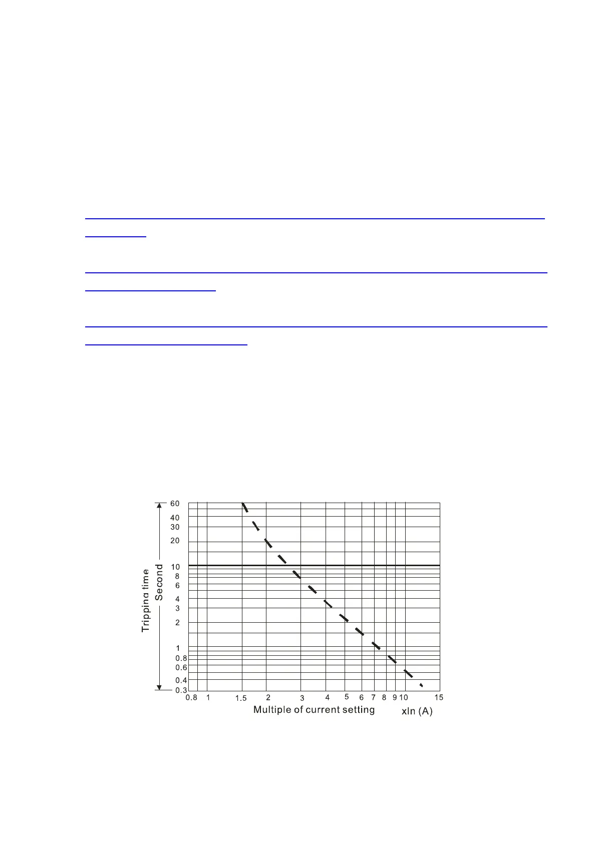
7. Thermal Overload Relay (TOR), for 230V / 460V / 690V models:
Choosing a thermal overload relay is based on whether its overload capability is appropriate for the CP2000.
The standard braking capacity of the CP2000 is 10%ED (Tripping time=10s). As shown in the figure below, a
460V, 110 kW CP2000 has a braking current of 126 A (refer to the tables in this section), so it can use the
thermal overload relay with a rated current of 50 A. The property of each thermal relay may vary among
different manufacturer, please carefully read specification.
Figure 7-5