Chapter 12 Description of Parameter SettingsCP2000
12.1-02-13
Settings Functions Descriptions
37
Error output selection 3
(Pr.06-25)
Active when Pr.06-25 is ON.
38
Error output selection 4
(Pr.06-26)
Active when Pr.06-26 is ON.
40
Speed reached
(including STOP)
Active when the output frequency reaches the setting frequency or
stopped.
44 Low current output This function needs to be used with Pr.06-71–Pr.06-73
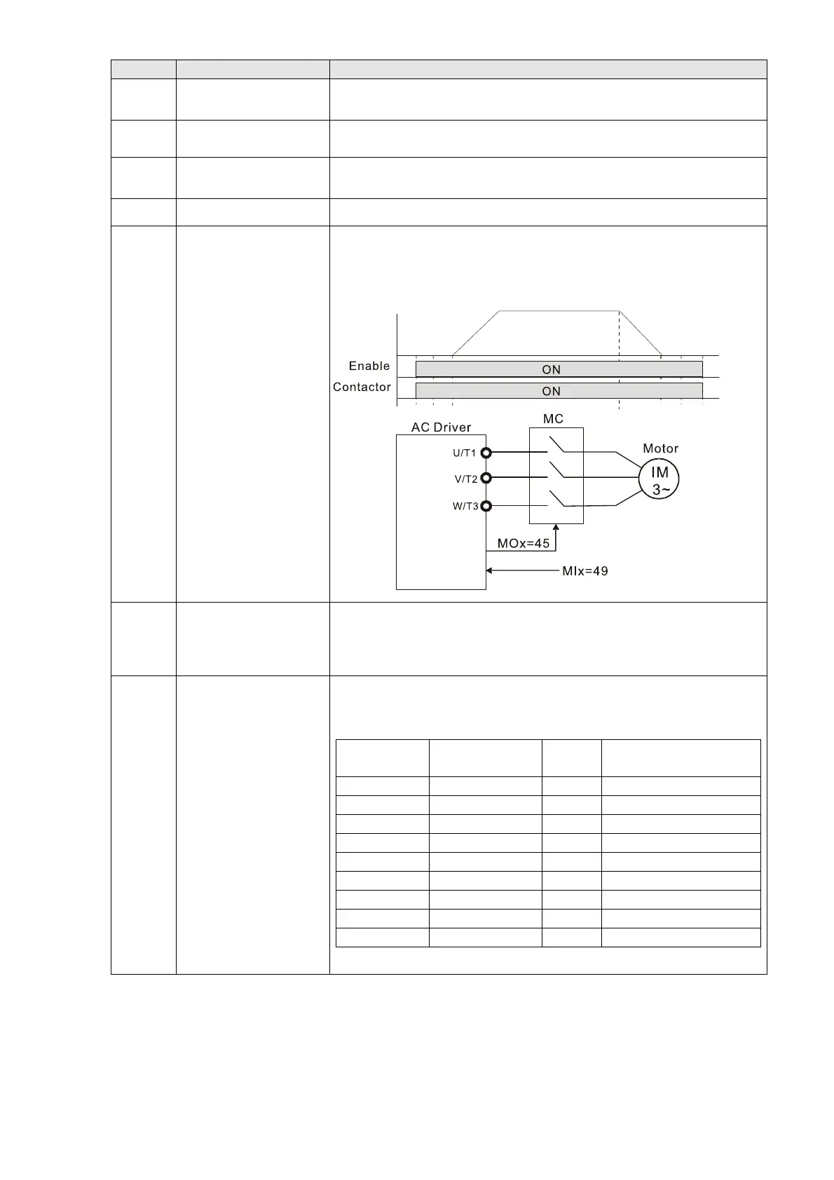
45
UVW output
electromagnetic valve
switch
Use this function with external terminal input = 49 (drive enabled) and
external terminal output = 45 (electromagnetic valve enabled), and
then the electromagnetic valve is ON or OFF according to the status of
the drive.
46 Master dEb output
When dEb rises at master, MO sends a dEb signal to the slave.
Output the message when the master triggers dEb. This ensures that
the slave also triggers dEb. Then slave follows the deceleration time
of the master to stop simultaneously with the master.
50
Output control for
CANopen
Control multi-function output terminals through CANopen.
To control RY2, set Pr.02-14 = 50.
The mapping table of the CANopen DO is shown in the following table:
Physical
terminal
Setting of related
parameters
Attribute Corresponding Index
RY1 Pr.02-13 = 50 RW The bit0 at 2026-41
RY2 Pr.02-14 = 50 RW The bit1 at 2026-41
RY3 Pr.02-15 = 50 RW The bit2 at 2026-41
MO10/RY10 Pr.02-36 = 50 RW The bit5 at 2026-41
MO11/RY11 Pr.02-37 = 50 RW The bit6 at 2026-41
RY12 Pr.02-38 = 50 RW The bit7 at 2026-41
RY13 Pr.02-39 = 50 RW The bit8 at 2026-41
RY14 Pr.02-40 = 50 RW The bit9 at 2026-41
RY15 Pr.02-41 = 50 RW The bit10 at 2026-41
Refer to Section 15-3-5 for more information.