EasyManuals Logo

Delta VFD150CP43B-21 User Manual

Delta VFD150CP43B-21
868 pages
To Next Page IconTo Next Page
To Previous Page IconTo Previous Page
Page #708 background imageLoading...
Page #708 background image
Chapter 16 PLC Function Applications│CP2000
16-25
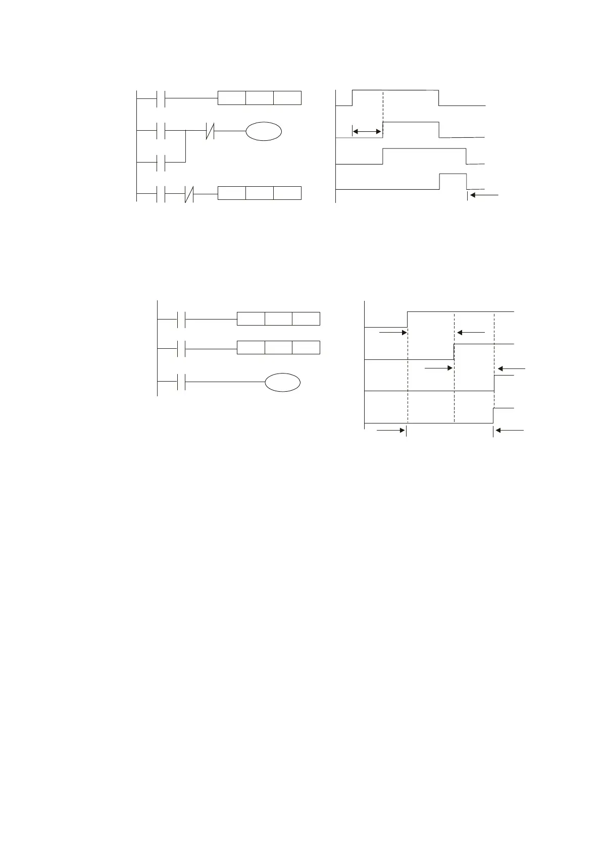
Example 11: The open/close delay circuit is composed of two timers; output Y4 will have a delay
whether input X0 is On or Off.
X0
Y4
TMR
T6
K30
X0
X0
Y4
TMR
T5
K50
T6
T5
3
ç§’
Y4
T5
T6
5
ç§’
Y4
Example 12: Extended timing circuit
In the circuit in the figure on the left, the total delay time from the moment input X0
closes to the time output Y1 is electrified is (n1+n2)*T, where T is the clock cycle. Timers:
T11, T12; clock cycle: T.
X0
Y1
TMR T12
Kn2
X0
T11
TMR
T11
Kn1
T12
Y1
T11
T12
n1*T
n2*T
(n1+n2)*T

Table of Contents

Questions and Answers:

Question and Answer IconNeed help?

Do you have a question about the Delta VFD150CP43B-21 and is the answer not in the manual?

Delta VFD150CP43B-21 Specifications

General IconGeneral
BrandDelta
ModelVFD150CP43B-21
CategoryDC Drives
LanguageEnglish

Related product manuals