Chapter 8 Option CardsMS300
157
Environment
ESD (IEC 61800-5-1, IEC 6100-4-2)
EFT (IEC 61800-5-1, IEC 6100-4-4)
Surge Test (IEC 61800-5-1, IEC 6100-4-5)
Conducted Susceptibility Test (IEC 61800-5-1, IEC 6100-4-6)
Operation: -10–50ºC (temperature), 90% (humidity)
Storage: -25–70ºC (temperature), 95% (humidity)
Shock / Vibration
Resistance
International standards:
IEC 61131-2, IEC 68-2-6 (TEST Fc) / IEC 61131-2 & IEC 68-2-27(TEST Ea)
8-2-4 Installation
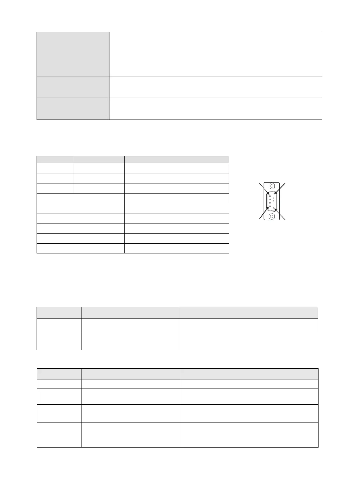
PROFIBUS DP Connector
Sending / receiving data P(B)
Sending / receiving data N(A)
8-2-5 LED Indicator & Troubleshooting
There are two LED indicators on the CMM-PD02: POWER LED and NET LED. POWER LED displays
the status of the working power. NET LED displays the connection status of the communication.
POWER LED
Power supply in normal status.
Check if the connection between the CMM-PD02
and the AC motor drive is normal.
The CMM-PD02 is not connected to
PROFIBUS DP bus.
Connect the CMM-PD02 to the PROFIBUS DP bus.
Invalid PROFIBUS communication
address
Set the PROFIBUS address of the CMM-PD02
between 1–125 (decimal).
The CMM-PD02 fails to
communicate with the AC motor
drive.
Switch off the power and check whether the CMM-
PD02 is correctly installed and normally connected
to the AC motor drive.