EasyManua.ls Logo

Delta VFD1A5MS43ANSAA User Manual

Delta VFD1A5MS43ANSAA
805 pages
To Next Page IconTo Next Page
To Previous Page IconTo Previous Page
Page #407 background imageLoading...
Page #407 background image
Chapter 12 Descriptions of Parameter SettingsMS300
398
00-20
Master Frequency Command Source (AUTO, REMOTE)
Default: 0
Settings
0: Inputs from digital keypad
1: Inputs from RS-485 communication
2: Inputs from external analog (refer to Pr.03-00, Pr.03-01)
3: Inputs from external UP / DOWN terminals
4: Pulse inputs without direction command
(refer to Pr.10-16 without direction)
5: Pulse inputs with direction command (refer to Pr.10-16)
6: CANopen communication card
8: Communication cards (CANopen card not included)
03-00
AVI Analog Input Selection
03-01
ACI Analog Input Selection
Default: 0
Settings
4: PID target value
5: PID feedback signal
1. Common applications for PID control:
Flow control: Use a flow sensor to feedback the flow data and perform accurate flow
control.
Pressure control: Use a pressure sensor to feedback the pressure data and perform
precise pressure control.
Air volume control: Use an air volume sensor to feedback the air volume data to achieve
excellent air volume regulation.
Temperature control: Use a thermocouple or thermistor to feedback temperature data for
comfortable temperature control.
Speed control: Use a speed sensor to feedback motor shaft speed or input another
machine speed as a target value for synchronous control.
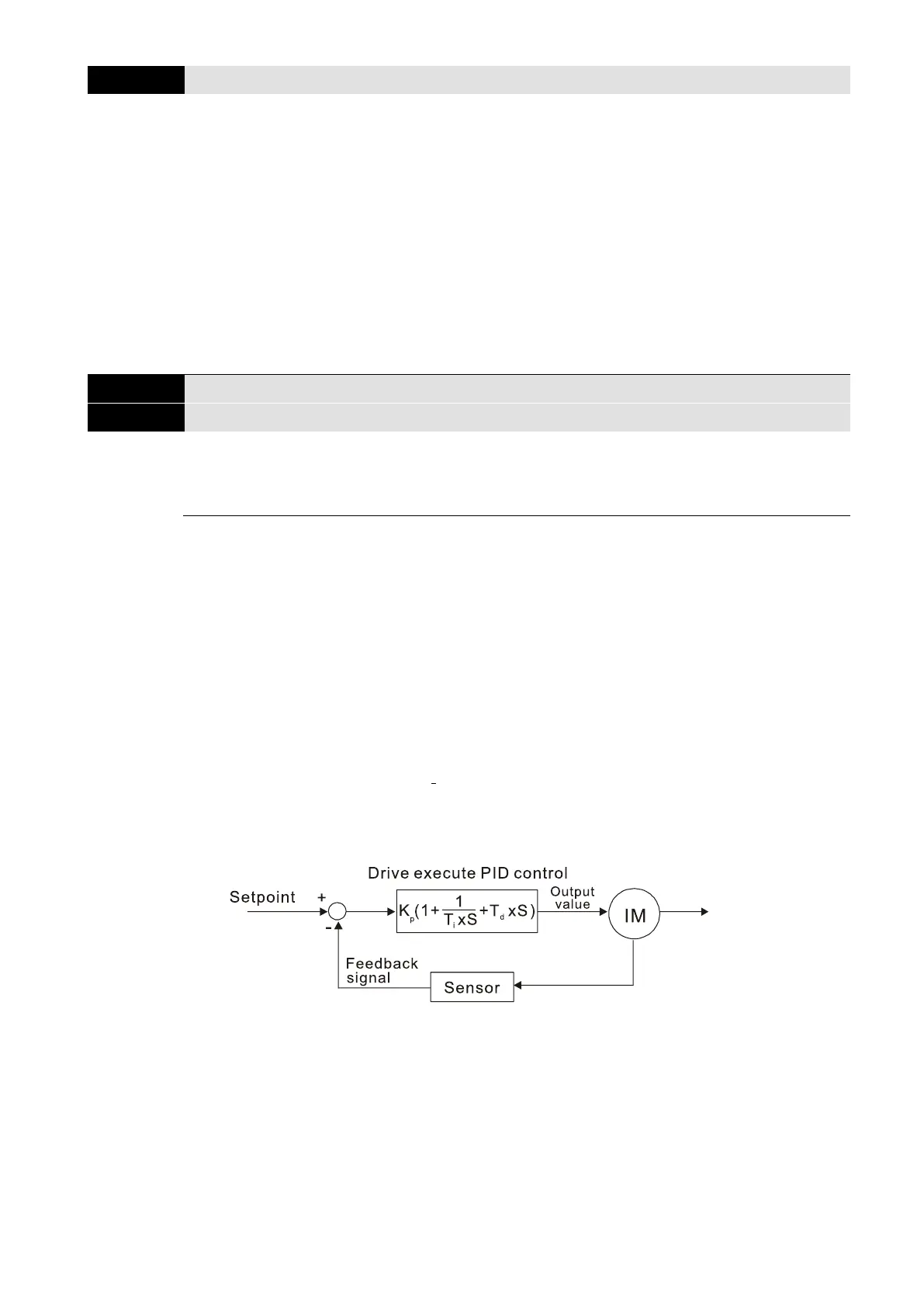
2. PID control loop:
K
P
Proportional Gain (P), Ti Integral Time (I), T
d
Differential Time (D), S Calculation
3. Concept of PID control:
Proportional gain (P):
The output is proportional to input. With only a proportional gain control, there is always a
steady-state error.

Table of Contents

Questions and Answers:

Delta VFD1A5MS43ANSAA Specifications

General IconGeneral
ModelVFD1A5MS43ANSAA
Cooling MethodFan Cooling
Enclosure RatingIP20
ManufacturerDelta
Control MethodV/F control, Sensorless vector control
Overload Capacity150% for 60 seconds
Protection FeaturesOver-voltage, Over-current, Overheat, Under-voltage, Ground Fault, Short Circuit
Communication InterfaceRS-485
Operating Temperature-10°C to 50°C
Input Voltage3-phase 380-480V AC
Storage Temperature-20°C ~ +60°C (-4°F ~ +140°F)

Summary

READ PRIOR TO INSTALLATION FOR SAFETY.

Chapter 3 Installation

3-1 Mounting Clearance

Specifies minimum clearances required for mounting the drive.

3-2 Airflow and Power Dissipation

Discusses airflow requirements and power dissipation for different frames.

Chapter 4 Wiring

4-1 System Wiring Diagram

Illustrates the overall system wiring diagram.

4-2 Wiring

Details the specific wiring procedures for input, output, and control terminals.

Chapter 5 Main Circuit Terminals

5-1 Main Circuit Diagram

Shows the diagram of the main circuit terminals.

5-2 Main Circuit Terminal Specifications

Details the specifications for main circuit terminals, including ring lug dimensions.

Chapter 7 Optional Accessories

7-1 Brake Resistors and Brake Units Used in AC Motor Drives

Provides specifications and selection tables for brake resistors and units.

7-2 Magnetic Contactor / Air Circuit Breaker and Non-fuse Circuit Breaker

Recommends magnetic contactors and circuit breakers based on drive models.

7-3 Fuse Specification Chart

Lists recommended fuse specifications for branch circuit protection.

7-4 AC / DC Reactor

Explains the function and installation of AC and DC reactors.

7-5 Zero Phase Reactors

Details zero phase reactors for interference suppression.

7-6 EMC Filter

Explains EMC filters for enhancing EMC performance.

7-14 Digital Keypad - KPC-CC01

Introduces the KPC-CC01 digital keypad, its interface, and function.

Chapter 10 Digital Keypad

10-1 KPMS-LE01 Keyboard Panel

Describes the physical layout and function of the KPMS-LE01 keypad.

10-2 Keypad Operation Process

Details the operational steps for using the keypad, including page selection and parameter settings.

Chapter 11 Summary of Parameter Settings

00 Drive Parameters

Lists parameters related to the AC motor drive identity code.

01 Basic Parameters

Details basic parameters for motor specifications like frequency, voltage, and current.

Chapter 17 Safe Torque Off Function

17-1 Basic Function Description

Provides a general description of the MS300's STO function and compliance.

17-2 Safe Torque Off Terminal Function Description

Details the STO related terminal functions and their descriptions.

17-7 Error Code and Troubleshooting Instructions

Provides error codes and troubleshooting steps for STO/STL alarms.

17-8 Test and Fault Confirmation

Guides the user through testing and confirming the STO function and related detection.

Related product manuals