Chapter 6 Control TerminalsMS300
44
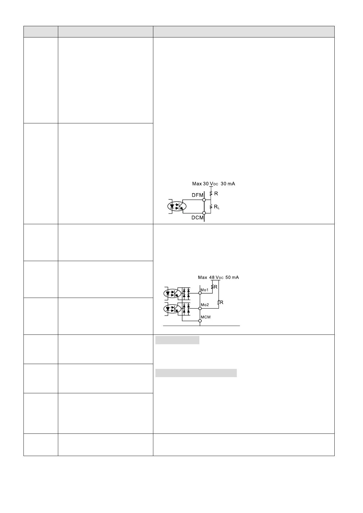
Digital frequency signal output
DFM uses pulse voltage as an output monitoring signal;
Duty-cycle: 50%
Min. load impedance R
L
: 1 kΩ / 100 pF
Max. current endurance: 30 mA
Max. voltage: 30 V
DC
± 1 %
(when 30 V
DC
/ 30 mA / RL=100 pF)
Max. output frequency: 33 kHz
Current-limiting resistor R: ≥ 1 KΩ
Output load impedance R
L
Capacitive load ≤ 100 pF
Resistive load ≥ 1 kΩ, resistance determines the output
voltage value.
DFM-DCM voltage = external voltage × (R
L
÷ (R
L
+R) )
Digital control /
Frequency signal common
(Sink)
Multi-function Output 1
(photo coupler)
The AC motor drive outputs various monitoring signals,
such as drive in operation, frequency reached, and overload
indication through a transistor (open collector).
Max. 48 V
DC
50 mA
Multi-function Output 2
(photo coupler)
Multi-function Output Common
(photo coupler)
Multi-function relay output 1
(N.O.) a
Resistive Load
3 A (N.O.) / 3 A (N.C.) 250 V
AC
5 A (N.O.) / 3 A (N.C.) 30 V
DC
Inductive Load (COS = 0.4)
1.2 A (N.O.) / 1.2 A (N.C.) 250 V
AC
2.0 A (N.O.) / 1.2 A (N.C.) 30 V
DC
To output different kinds of monitoring signals such as
motor drive in operation, frequency reached, and overload
indication.
Multi-function relay output 1
(N.C.) b
Multi-function relay common
Potentiometer power supply
Power supply for analog frequency setting: +10.5 ± 0.5 V
DC
/ 20 mA