Chapter 7 Optional AccessoriesMS300
51
VFDB2015 / 2022 / 4030 / 4045 / 5055 Braking Modules Instruction Sheet
http://www.deltaww.com/filecenter/Products/download/06/060101/Option/DELTA_IA-
MDS_VFDB_I_EN_20070719.pdf
VFDB4110 / 4160 / 4185 Braking Modules Instruction Sheet
http://www.deltaww.com/filecenter/Products/download/06/060101/Option/DELTA_IA-MDS_VFDB4110-
4160-4185_I_EN_20101011.pdf
VFDB6055 / 6110 / 6160 / 6200 Braking Modules Instruction Sheet
http://www.deltaww.com/filecenter/Products/download/06/060101/Option/DELTA_IA-MDS_VFDB6055-
6110-6160-6200_I_TSE_20121030.pdf
5. The selection tables are for normal usage. If the AC motor drive requires frequent braking, increase the Watts
by two to three times.
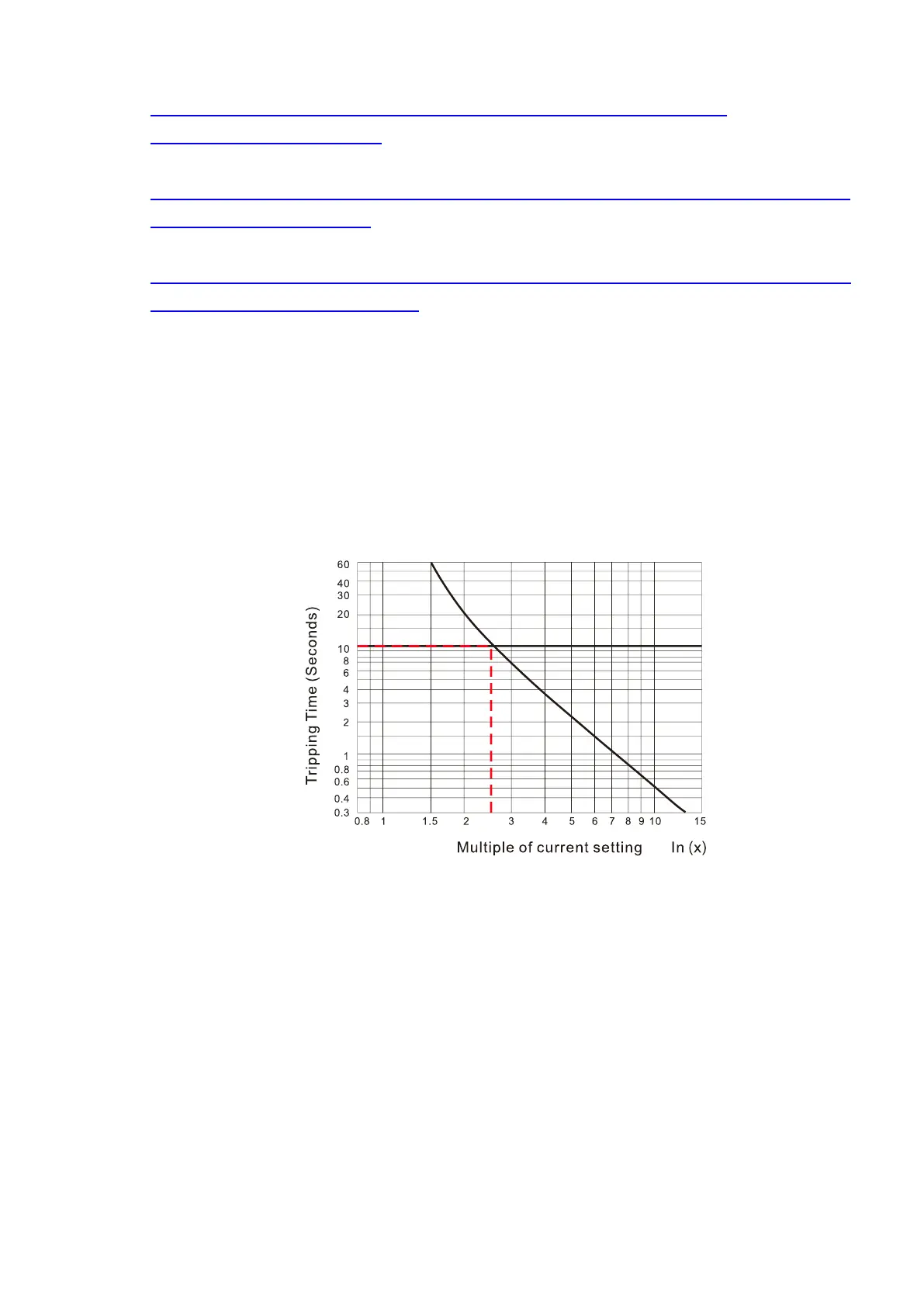
6. Thermal Overload Relay (TOR):
Thermal overload relay selection is based on its overload capacity. A standard braking capacity of the MS300
is 10% ED (Tripping time = 10 s). As shown in the figure below, a 460V, 1 kW MS300 required the thermal
relay to take 260% overload capacity for 10 seconds (hot starting) and the braking current is 24A. In this
case, select a thermal overload relay rated at 10 A (10 × 260% = 26 A > 24 A). The property of each thermal
relay may vary among different manufacturers. Carefully read the specification before using it.
Figure 7-3
 Loading...
