Chapter 12 Descriptions of Parameter SettingsMS300
410
Calculation formula:
Output frequency = Fmax (Pr.01-00) × error% ((PID reference value (Pr.00-20 / Pr.00-30) – PID
feedback (Pr.08-00)) × Pr.08-01.
When Pr.08-65 ≠ 0, the internal calculation of the proportional gain reduces by 100 times, that is,
when Pr.01-00 Fmax = 60 Hz, error = 100%, Pr.08-01=1.00, then the output frequency is ‟0.01”
times the Pr.01-00 Fmax. Therefore, the output frequency = 60 × 100% × 0.01=0.6 Hz.
Calculation formula:
Output frequency = Fmax (Pr.01-00) × error% ((PID reference value (Pr.08-66) – PID feedback
value (Pr.08-00)) × Pr.08-01 × 0.01.
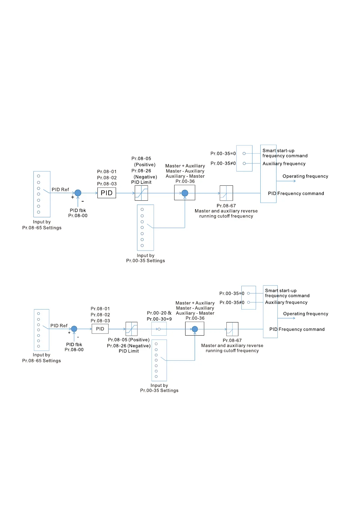
When Pr.08-65 = 0, the PID controller architecture shows as the diagram below:
When Pr.08-65 ≠ 0, the PID controller architecture shows as the diagram below:
When Pr.08-65 is not set to 0, Pr.00-20 is automatically set to 9.
When Pr.08-65 is set to 1, set the PID command through Pr.08-66; when Pr.08-65 is not set to 1,
Pr.08-66 displays the PID command.
When Pr.08-65 is set to 2, 4, and 6, the corresponding communication address is C2003H.