EasyManuals Logo

Delta VFD2A8MS21ANSAA User Manual

Delta VFD2A8MS21ANSAA
805 pages
To Next Page IconTo Next Page
To Previous Page IconTo Previous Page
Page #692 background imageLoading...
Page #692 background image
Chapter 16 PLC Function ApplicationsMS300
683
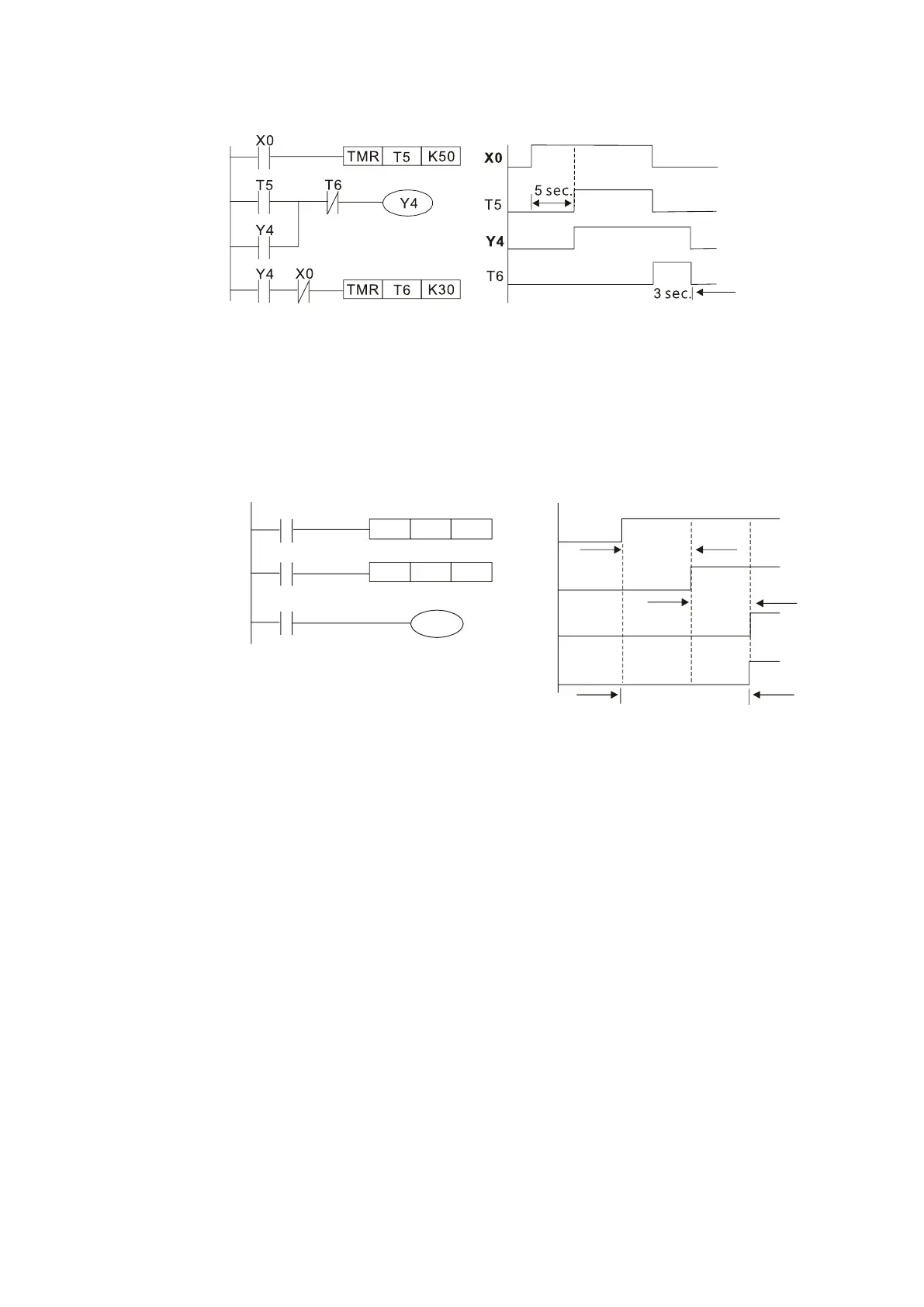
Example 11: The open/close delay circuit is composed of two timers; output Y4 has a delay no matter
input X0 is ON or OFF.
Figure 16-48
Example 12: Extended timing circuit
In the circuit in the ladder diagram on the left, the total delay time from the moment input
X0 closes to the time output Y1 is electrified is (n1+n2) × T, where T is the clock cycle.
The timers are T11 and T12, and the clock cycle is T.
X0
Y1
TMR T12
Kn2
X0
T11
TMR
T11
Kn1
T12
Y1
T11
T12
n1*T
n2*T
(n1+n2)*T
Figure 16-49

Table of Contents

Other manuals for Delta VFD2A8MS21ANSAA

Questions and Answers:

Question and Answer IconNeed help?

Do you have a question about the Delta VFD2A8MS21ANSAA and is the answer not in the manual?

Delta VFD2A8MS21ANSAA Specifications

General IconGeneral
BrandDelta
ModelVFD2A8MS21ANSAA
CategoryDC Drives
LanguageEnglish

Related product manuals