Chapter 8 Option CardsC2000 Plus
8-35
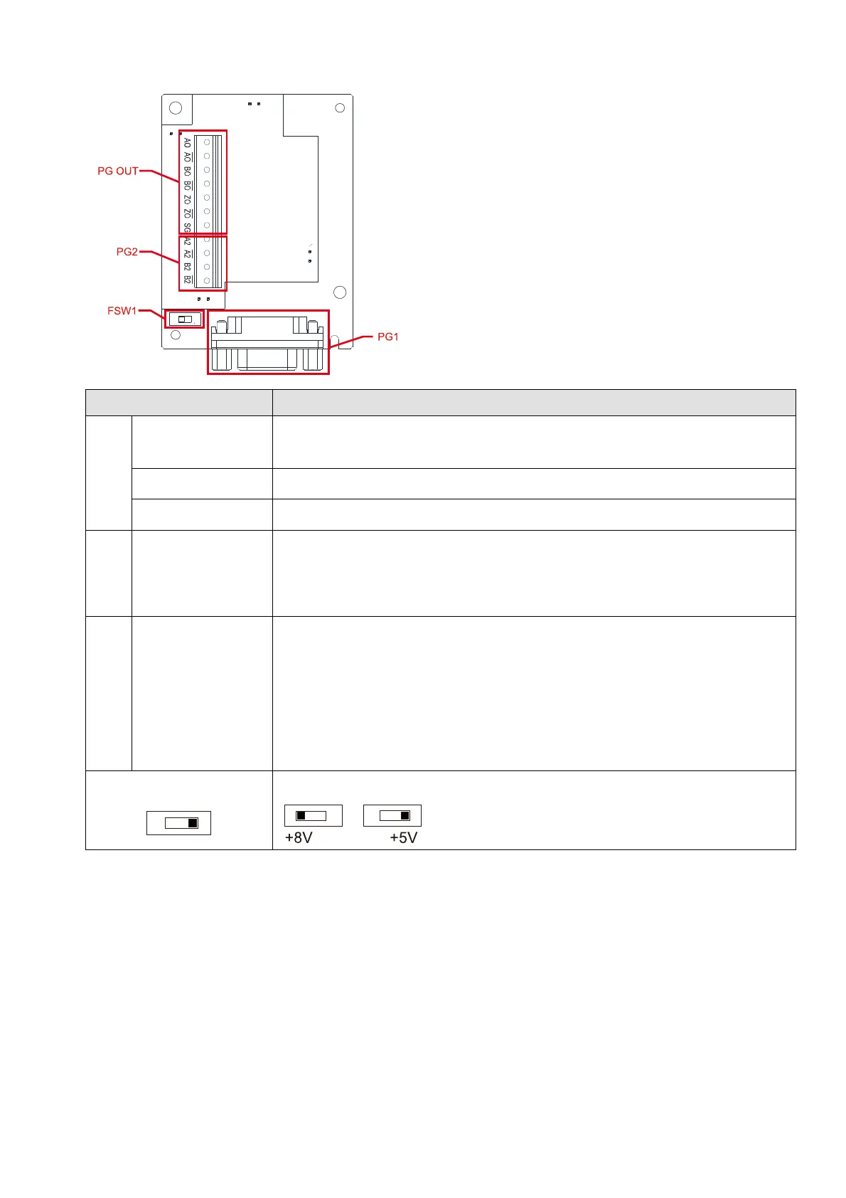
8-12-2 Terminal Specification
Terminals Descriptions
PG1
VP
Power output voltage: +5V / +8V 5% (+5V / +8V determined by FSW1)
*1
Max. output current: 200 mA
DCM
Digital control / Frequency signal common
DATA+, DATA- Read and process the encoder data transmission
PG2
A2, /A2,
B2, /B2
Pulse Input signal (Line Driver or Open Collector)
Open Collector Input Voltage: +5V – +24V
*2
It can be single-phase or two-phase input
Max. input frequency: 300 kHz
PG
OUT
AO, /AO,
BO, /BO,
ZO, /ZO,
SG
PG Card output signals. It has division frequency function: 1–255 times
Max. output voltage for Line driver: 5 V
DC
Max. output current:15 mA
Max. output frequency: 600 kHz ± 5%
SG is the GND of PG card. It is also the GND of position machine or PLC
to make the output signal to be the common pivot point.
FSW1
Use FSW1 to switch the power of VP: +5V/+8V
*1
NOTE:
1. The current input voltage for Tamagawa encoder is +5V, ensure to switch to +5V before the
installation. The voltage +8V is reserved for the power demand of other encoders in the future.
2. Open Collector application, input current 5–15 mA to each set then each set needs one pull-up
resistor. If input voltage of open collector is 24V, the power of encoder needs to be connected
externally. Refer to diagram 2 of PG2.