Chapter 5 Main Circuit TerminalsC2000 Plus
5-3
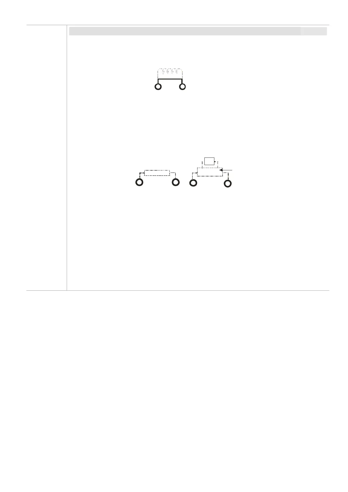
Terminals for connecting DC reactor, external brake resistor and DC circuit
Use the terminals, as shown in Figure 5-2, to connect a DC reactor to improve the
power factor and reduce harmonics. A jumper is connected to these terminals at the
factory. Remove that jumper before connecting to a DC reactor.
+1
+2
DC reactor (optional)
Figure 5-2
Install an external brake resistor for applications in frequent deceleration to stop, short
deceleration time (such as high frequency operation and heavy load operation), too
low braking torque, or increased braking torque.
B1
B2
BR
+
-
VFDB
Brake resistor
(optional)
Brake resistor
(optional)
Brake unit
(optional)
Figure 5-3
The external brake resistor of Frame A, B and C should connect to the terminals (B1,
B2) of AC motor drives.
For those models without built-in brake resistor, please connect external brake unit
and brake resistor (both of them are optional) to increase brake torque.
When the terminals +1, +2 and - are not used, leave the terminals open.
DC+ and DC- are connected by common DC bus, refer to Section 5-1 (Main Circuit
Terminal) for the wiring terminal specification and the wire gauge information.
Refer to the VFDB manual for more information on wire gauge when installing the
brake unit.