DEMA
®
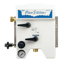
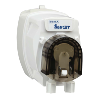
MODEL 693T FOAM STATION II
INSTALLATION INSTRUCTION
I-747 Page 1 of 8
Rev. E-40261 11/13/14
1. PARTS CHECKLIST:
ITEM DESCRIPTION QTY.
A.
Foam Station Assembly 1
B.
¼” ID Tubing & Foot Strainer 1
C.
3/8” ID Tubing & Foot Strainer 1
D.
Ceramic Weight (For ¼” ID Tubing) 1
E.
Ceramic Weight (For 3/8” ID Tubing) 1
F.
Metering Tip Kit 1
G.
#10 Screw & Anchor Kit Set (Total: 4 Screws & 4 Anchors) 1
H.
Label Card 1
2. INSTALLATION:
This product is designed only to be used as described in this instruction sheet. Adhere to all warnings and
cautions identified in this document.
WARNING: Installations must conform to all local and national plumbing codes and use
approved backflow prevention and pressure relief devices where required.
ALWAYS DISCONNECT DISPENSER FROM WATER SOURCE WHEN DISPENSER
IS NOT IN USE.
Always read SDS for all chemicals used and follow personal protective guidelines.
A. Mounting and Water Supply:
Locate mounting holes on a permanent vertical wall. Drill all holes into the drywall using a ¼” diameter bit for use with
the included #10 screw and anchor set. (If mounting unit to wood and you do not plan to use the included anchors, drill
1/8” diameter holes.) Insert the anchors into drilled holes and hammer them into the wall until they are flush with face
of wall. Assemble the #10 screws with a phillip screwdriver into the anchors for the keyhole slots so the screw heads are
sticking out of the wall approximately ½”. Mount the unit by inserting the screw heads through the keyhole slots and
tightening the screws. Secure the unit by inserting screws into the lower 2 holes.
The water inlet is equipped with a female garden hose fitting. The fitting may be removed to permit direct connection to
3/8” NPT pipe. Note: Apply pipe dope, hand tighten, and then turn 1-1/2 times with a wrench. DO NOT OVER
TIGHTEN.
WARNING: Do not use Teflon tape to seal internal plastic threads as the extra thickness of the tape may cause
the plastic to crack. Use non-welding liquid sealant instead.
WARNING: Water supply should not exceed 125 psi and water temperature must not exceed 150°F.
B. Outlet Connection:
Connect the discharge hose to the garden hose fitting. NOTE: Be sure to clamp garden hose onto wall
approximately 1 ft. below the unit, (Clamps, screws, & anchors are not supplied.) Attach shut-off valve to the
discharge end of the hose. See Table 1 for hose limitations.
C. Chemical Supply:
WARNING: USE CARE WHEN HANDLING HAZARDOUS CHEMICALS.
Place the chemical container in a convenient location not more than six feet below the Foam Station as greater lifts will
reduce injection capabilities. The top of the container should not be above the Foam Station. Cut the vinyl tube to any
convenient length that will allow the tubing to reach the bottom of the container. Drop the tubing end with the strainer