EasyManuals Logo

DEMA D5M Series User Manual

DEMA D5M Series
99 pages
To Next Page IconTo Next Page
To Previous Page IconTo Previous Page
Page #90 background imageLoading...
Page #90 background image
Annex
86
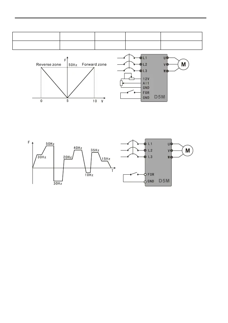
As shown in the curve of Figure F-3.
Parameter setting
P001=1
P002=1
P072=50
P073=50
P074=0
P075=1
P076=1
Figure F-3 Motor Forward/Reverse Curve and Wiring Diagram
4. Internally controlled 8-segment speed operation
Realize those shown in the curve of Figure F-4 and stop internally controlled 8-segment
speed after operating by one cycle.
Figure F-4 Operation Curve and Wiring Diagram of Internally Controlled 8-segment Speed
Parameter setting
P080=1
P003=30
P086=50
P087=30
P088=20
P089=40
P090=10
P091=35
P092=15
P082=36
P081=0
P014=5
P015=5
P001=1
P083=0
P044=1
P101-P108=15
[Description] 1) Operating time of each segment speed is set via P101-P108=15;
2) Automatic cycle P081=1;
3) After giving operating instruction, stop after operating by one cycle as per set
curve.

Table of Contents

Questions and Answers:

Question and Answer IconNeed help?

Do you have a question about the DEMA D5M Series and is the answer not in the manual?

DEMA D5M Series Specifications

General IconGeneral
BrandDEMA
ModelD5M Series
CategoryInverter
LanguageEnglish

Related product manuals