Page 27
HYDRAULIC PARTS LIST
Down Pressure Operation:
The amount of down pressure can be seen on the hydraulic
pressure gauge. Only use as much down pressure required
to keep the coulter at the proper depth. Do not exceed
1500 PSI to prevent the wings from lifting up the center
section.
Activating the Down Pressure
1. After the toolbar has been fully unfolded press the
pressure down button.
2. During operation hydraulic pressure will now show up
on the gauge. (If the bar is equipped with the automatic
down pressure and kick up switch, lower the three
point and press the pressure down button. Now the
bar is in automatic mode, raise and lower the three
point when the switch is set to activate down pressure
and kick up.)
3. To deactivate the down pressure, press and hold the
kick up button until the wings are raised.
* NOTE WHEN IN 60’ MODE IF THE OUTER
RETRACT BUTTON IS PRESSED THE PRESSURE
DOWN WILL NOT WORK UNTIL OUTER EXTEND
BUTTON HAS BEEN PRESSED AGAIN.
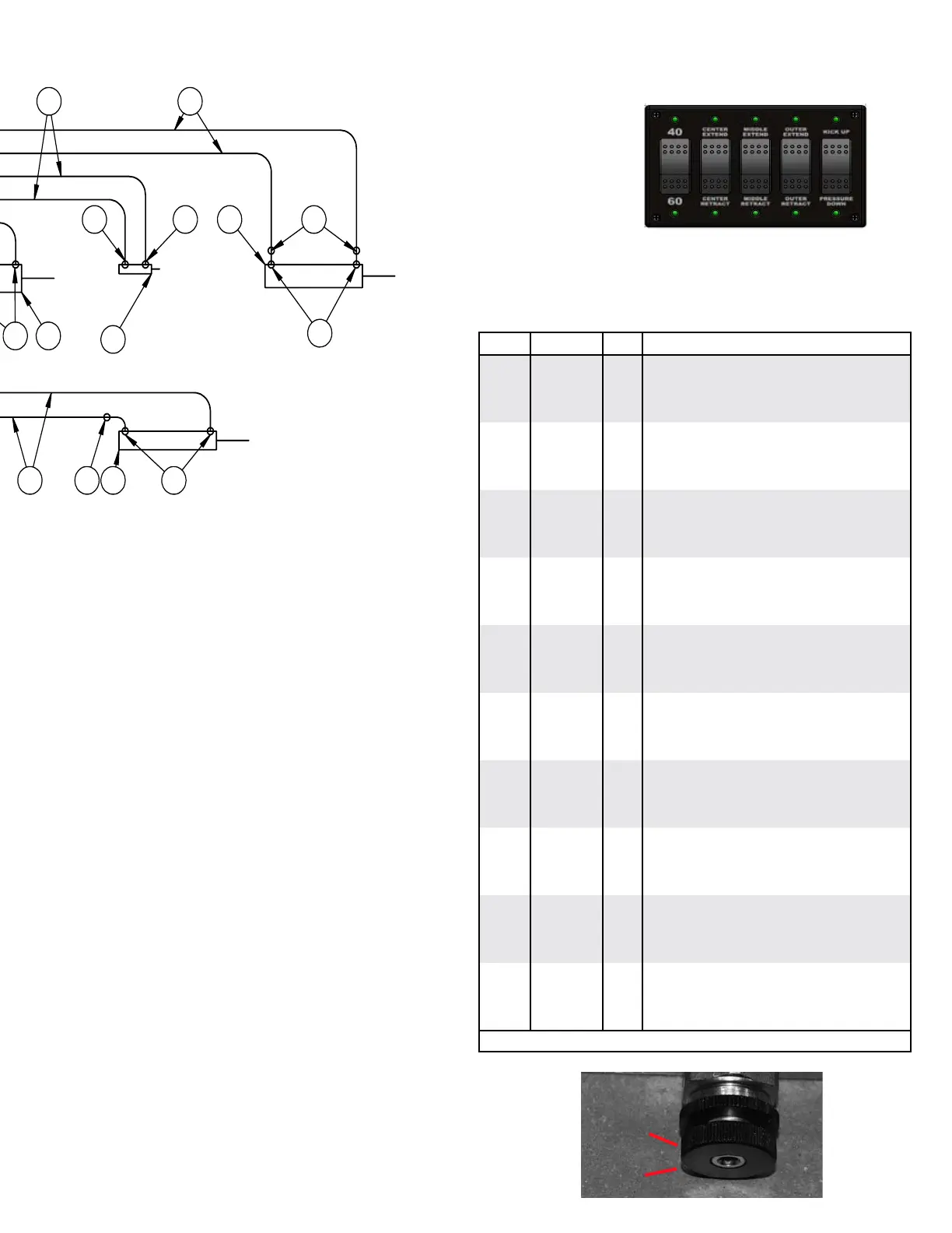
Adjusting the down pressure:
1. Loosen the jam nut (A)
2. To increase pressure turn the screw clockwise one
turn at a time. (B)
3. To lower the pressure turn the screw counter clockwise
one turn at a time.
4. Once the desired pressure is reached tighten the jam
nut.
A
B
+'331
%5$1&+(67<3
+'361
'76
)+
,1/,1()86(+2/'(5
326,7,21:($7+(53$.
&211(&72572/,0,76:,7&+
237,21$/$0363('(67$/02817
7+(,1)250$7,21&217$,1(',17+,6
'5$:,1*,67+(62/(3523(57<2)
6&253,217(&+12/2*,(6/7'$1<
5(352'8&7,21,13$5725$6$:+2/(
:,7+2877+(:5,77(13(50,66,212)
6&253,217(&+12/2*,(6/7',6
352+,%,7('
35235,(7$5<$1'&21),'(17,$/
02',),('
70
-2%12
/
,
+
*
)
(
'
&
%
$
',0(16,216$5(,1,1&+(6
$1*8/$5
7:23/$&('(&,0$/
7+5((3/$&('(&,0$/
)2853/$&('(&,0$/
)5$&7,21$/
0$7(5,$/
),1,6+
'5$:1%<
&5($7('
7,7/(
':*12
5(9
2)
$660$/
-
0
.
/DYDO&UHVFHQW.DPORRSV%&9&3
7HO)D[
$VVHPEO\ZLWK9DOYH+DUQHVV
6&$/(
6+((7
ITEM PART # QTY DESCRIPTION
1
05198
2 COUPLER RUBBER CAP
2
05203
10 #6 FEMALE JIC TO #6 MALE JIC (2X) TEE
3
05212
2 .25” X 18.50” HYD HOSE
4
05243
14 #6 MALE O-RING TO #6 JIC MALE STR
5
07072
2 #6 MALE JIC TEE
6
11143
4 #6 O-RING X #6 MALE JIC 90°
7
12374
2 #6 JIC BULKHEAD 45°
8
13255
4 #6 JIC ORIFICE .045
9
13548
2 #8 MALE O-RING TO #8 JIC MALE STR
10
13631
2 #6 JIC ORIFICE .060
11
13888
2 HYDRAULIC QUICK COUPLER #8 O-RING
12
15082
2 CYLINDER HYD, 3.00 X 6.00
13
15084
2 CYLINDER HYD, 3.00 X 20.00
14
15158
16 #8 O-RING X #6 MALE JIC 90°
15
15257
2 CYLINDER HYD 4.00 X 14.00
16
15277
6 .375” X 168” HYD HOSE
17
15279
8 .375” X 108” HYD HOSE
18
15466
2 CYLINDER HYD 2.00 X 3.00
19
15494
2 CYLINDER HYD, 4.00 X 20.00
20
15495
2 CYLINDER HYD, 3.50 X 20.00
21
15496
4 #10 O-RING X #6 MALE JIC 90°
22
15497
4 .375” X 252” HYD HOSE
23
15498
4 .25” X 192” HYD HOSE
24
15499
1 60’ TOOLBAR HYDRAULIC BLOCK
25
15502
2 #6 FEMALE JIC SWIVEL X #4 FEMALE PIPE
26
15766
1 CONTROLLER F/ 60’ TOOLBAR TRAILER
-
15516
1 WIRE HARNESS 30’ F/ CONTROLLER
27
15548
2 GAUGE HYD 3000 PSI #4 PIPE
28
15700
2 .50” X 384” HYD HOSE
29
15701
4 .375 X 72” HYD HOSE
Please order replacement parts by PART NO., DESCRIPTION, and COLOR
26
1
P
T
2
4
3
5
6
G3
7
8
9
10
11
12
G4
 Loading...