Page 29
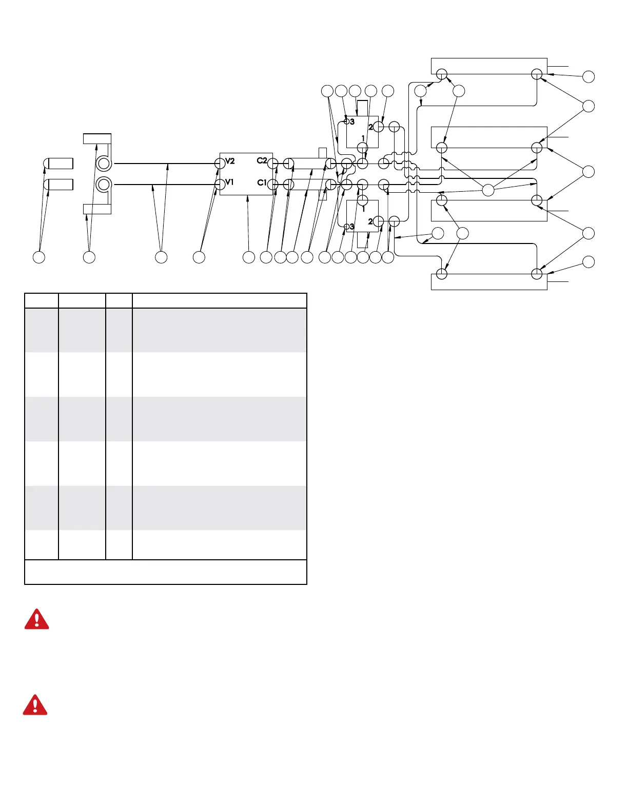
FOLDING HYDRAULIC PARTS LIST
ITEM PART # QTY DESCRIPTION
1
05198
2 COUPLER RUBBER CAP
2
05203
6 #6 FEMALE JIC TO #6 MALE JIC (2X) TEE
3
05212
2 .25” X 18.50” HYD HOSE
4
05243
6 #6 MALE O-RING TO #6 JIC MALE STR
5
07582
1 HYD PO CHECK VALVE
6
12328
2 #6 MALE O-RING TO #6 MALE JIC (2X) TEE
7
13888
2 QUICK COUPLER #8 O-RING
8
15083
2 CYLINDER HYD, 3.50 X 20.00
9
15084
2 CYLINDER HYD, 3.00 X 20.00
10
15158
8 #8 O-RING X #6 MALE JIC 90°
11
15277
4 .375” X 168” HYD HOSE
12
15279
4 .375” X 108” HYD HOSE
13
15306
4 #6 MALE O-RING X #6 FEMALE JIC
14
15311
2 #6 MALE JIC X #4 MALE O-RING 90°
15
15703
2 FLOW CONTROL VALVE
16
15704
2 SEQUENCE VALVE
17
15705
2 .375” X 384” HYD HOSE
Please order replacement parts by PART NO., DESCRIPTION, and
COLOR.
Initial Operation:
WARNING: To avoid personal injury or property
damage, observe the following instructions. Do not
attempt to operate the toolbar until the hydraulic lines
and cylinders are completely charged with hydraulic fluid.
Failure to do so may cause erratic and unpredictable
toolbar operation that may cause personal injury and
physical damage to the toolbar.
WARNING: To avoid personal injury or property
damage, observe the following instructions. Make
sure whenever operating the toolbar that no one in is
line of unfolding and no electric lines or tree branches
will come in contact with the toolbar during folding or
unfolding.
Unfolding the toolbar :
When doing this the first time it would be advisable to
have another person standing safely behind the fertilizer
applicator to ensure that none of the hoses or coulters are
interfering with the toolbar operation and that the toolbar
is correctly unfolding.
Note: Do not select more than one switch at a time.
Note: Tractor hydraulic flow control lever should be
reduced to 25% for initial start up. Increased oil
ow may be required on certain model tractors.
(See tractor manual for location and procedure)
1. Fully extend the kick up cylinders and bar lift
cylinders.
3. To unfold the toolbar move the hydraulic lever connected
to the fold cylinders in the tractor to the extend
position
4. Activate down pressure (see pg. 30)
5. Unit is now ready for field operation
After the toolbar has been unfolded the first time, stop and
take a moment to make sure all hoses are routed correctly
and there are no interference problems.
Folding the toolbar:
1. Move the hydraulic lever connected to the kick up
cylinders and the lift cylinders in the tractor to the
extend position.
3. Once fully extended move the hydraulic lever connected
to the fold cylinders in the tractor to retract position
40’ TOOLBAR HYDRAULICS SCHEMATIC AND OPERATION
 Loading...